Eureka AIR delivers breakthrough ideas for toughest innovation challenges, trusted by R&D personnel around the world.

Fastening device

a technology of fastening device and screw, which is applied in the direction of threaded fasteners, fastening means, mechanical devices, etc., can solve the problems of unnecessarily difficult fixing operation, and achieve the effect of reducing the insertion force of the screw and enhancing the rigidity of the second regulating piece itsel

Inactive Publication Date: 2008-07-03
PIOLAX CO LTD
View PDF2 Cites 17 Cited by
  • Summary
  • Abstract
  • Description
  • Claims
  • Application Information

AI Technical Summary

Benefits of technology

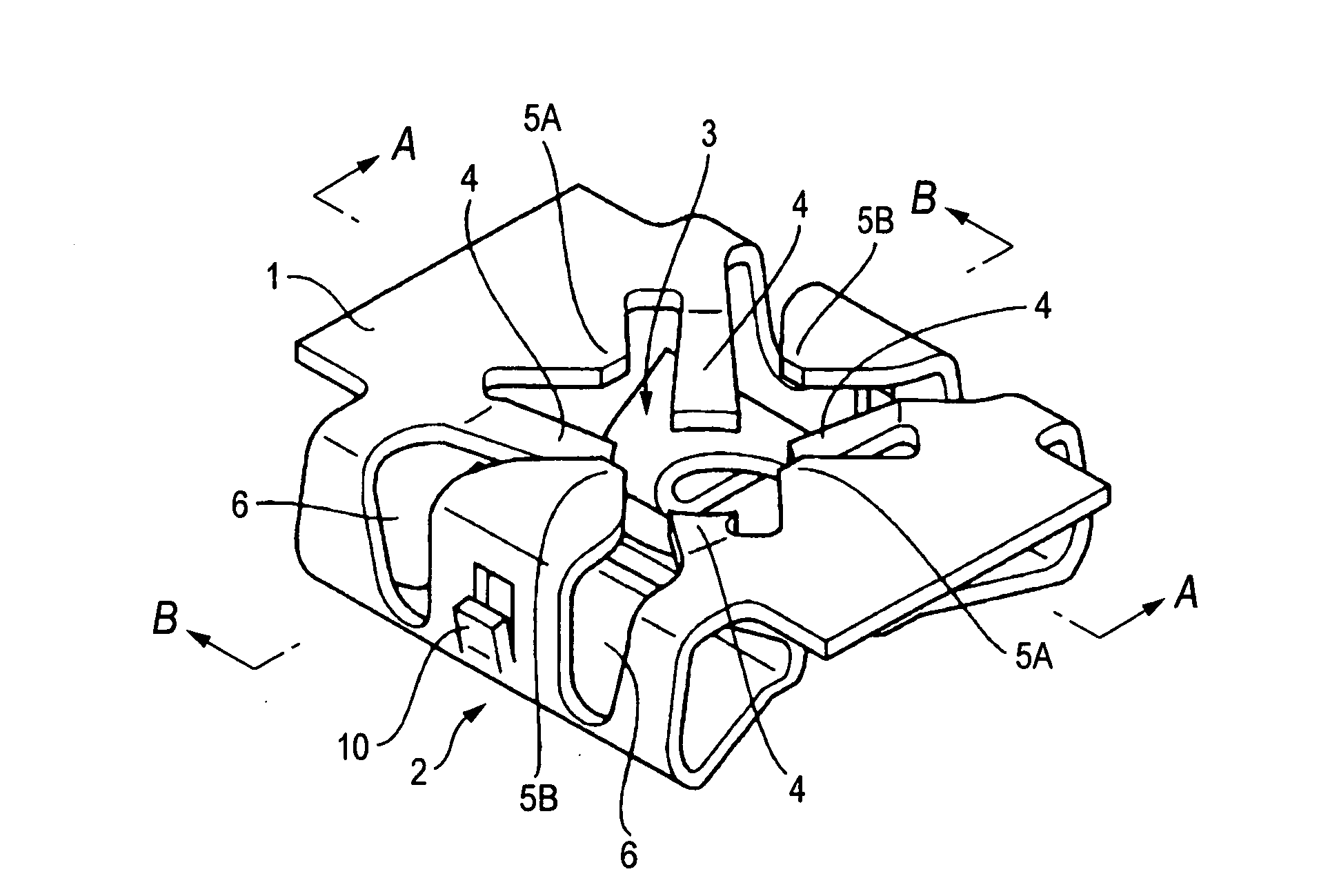
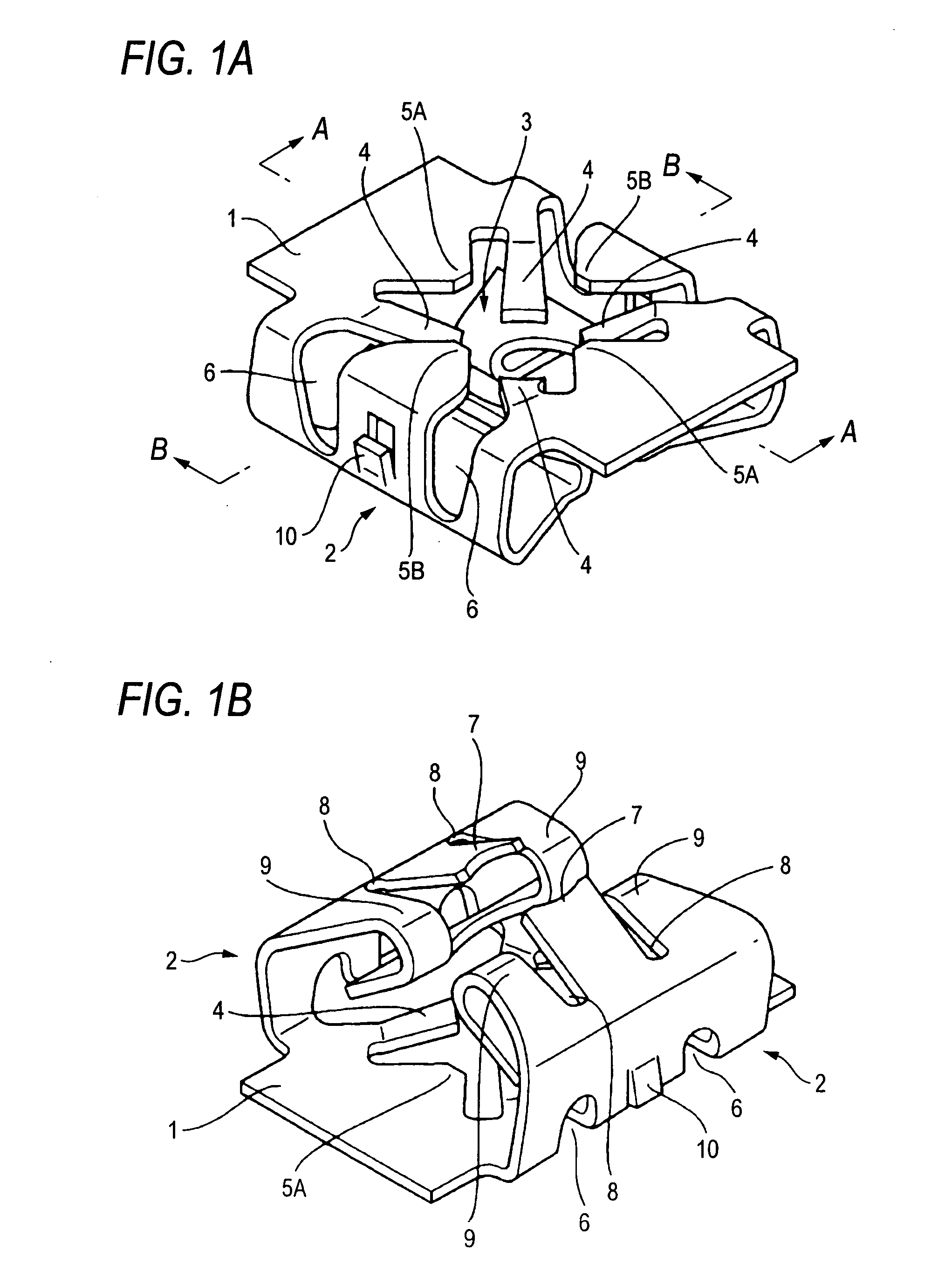
[0015]According to the first aspect of the invention, when inserting the screw into the first screw hole defined by the two pairs of first elastic securing pieces, without rotating the screw as in the conventional fastening device, the screw. can be inserted linearly because the two pairs of first elastic securing pieces are easily flexed, and also, in the screw insertion operation, the insertion attitude of the screw can be regulated by the first guide defined by the first regulating pieces. Therefore, when the fastening device of the invention is compared with the conventional fastening device, the efficiency of the fixing operation can be enhanced greatly.
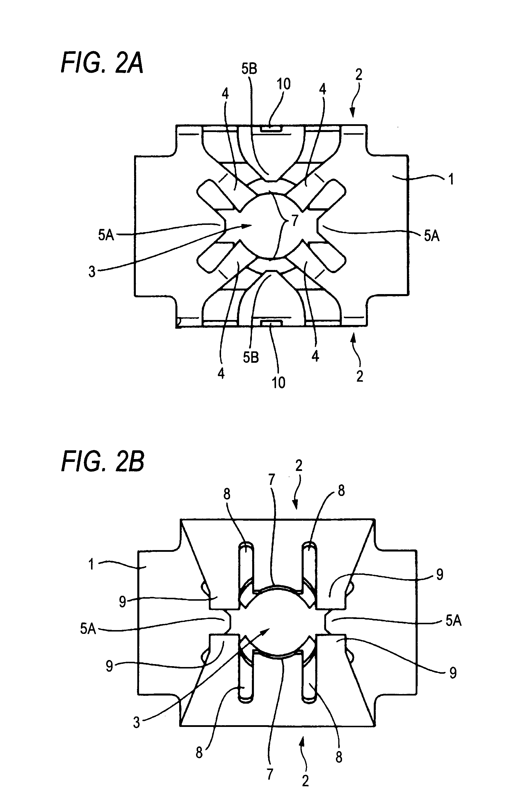
[0016]According to the second aspect of the invention, since the two pairs of first elastic securing pieces are extended on the diagonal lines, the length dimensions of the respective first elastic securing pieces can be set as long as possible. This can facilitate the flexing of the first elastic securing pieces and thus can reduce the insertion force of the screw.
[0017]According to the third aspect if the invention, since the second elastic securing pieces for defining the second screw hole are set on the side of the pair of leg piece portions as well, the screw can be supported by the first and second screw holes formed in upper and lower two positions. This not only can effectively prevent the screw from loosening but also can facilitate the flexing of the second elastic securing pieces to thereby allow the linear insertion of the screw. Therefore, the efficiency of the fixing operation can be enhanced.
[0020]According to the sixth aspect of the invention, since the bent leading end portions of the two pairs of regulating pieces are connected together on their respective sides, not only the regulation block can be spread but also the rigidity of the second regulating pieces themselves can be enhanced.
[0021]According to the seventh aspect of the invention, since the dimension between the upper ends of the pair of leg piece portions as well as the dimension between the two first regulating pieces, which are respectively separated from their associated leg piece portions through their associated slits, are respectively set larger than the mounting hole of the fixing member, simply by pressure inserting the fastening device itself into the mounting hole of the fixing member, the fastening device can be mounted. This can eliminate the need to spread a pair of leg piece portions using a screw as in the conventional fastening device. Thus, the insertion force of the screw can be reduced in this respect as well.

Problems solved by technology

However, this tends to make the fixing operation unnecessarily difficult.

Method used


Image

  • Fastening device
  • Fastening device
  • Fastening device

Examples


Embodiment Construction

[0033]According to the present invention, there is provided a fastening device for fixing a member to be fixed to a fixing member through a screw, including: a top plate portion; and, a pair of leg piece portions respectively suspended from the two side edges of the top plate portion, wherein the top plate portion includes two pairs of first elastic securing pieces disposed opposed to each other for defining a first screw hole formed in the screw, and two pairs of regulating pieces respectively interposed between the first elastic securing pieces for defining a first guide hole having a diameter larger than the first screw hole. According to this structure, when inserting the screw into the first screw hole which is defined by the two pairs of first elastic securing pieces, without rotating the screw, by flexing the first elastic securing pieces respectively, the screw can be inserted linearly into the first screw hole. This can facilitate the insertion operation of the screw.

[0034]...


PUM


Abstract

A fastening device for fixing a member to be fixed to a fixing member through a screw, the fastening device includes: a top plate portion; and a pair of leg piece portions respectively suspended from the two side edges of the top plate portion, wherein the top plate portion includes two pairs of first elastic securing pieces disposed opposed to each other for defining a first screw hole formed in the screw, and two pairs of regulating pieces respectively interposed between the first elastic securing pieces for defining a first guide hole having a diameter larger than the first screw hole.

Description

BACKGROUND OF THE INVENTION[0001]1. Field of the Invention[0002]The present invention relates to a fastening device for fixing, for example, a car trim to a body panel through a screw.[0003]2. Description of the Related Art[0004]Conventionally, this kind of fastening device, although not shown specifically, is molded of an elastic metal thin plate such as a spring steel plate into an integral body which includes a top plate portion having a flat plate shape and a pair of leg piece portions respectively suspended from the two side edges of the top plate portion and having a U-like shape. specifically, the top plate portion includes a nut hole which is formed in the central portion thereof and also into which a screw can be threadedly engaged; and, the leg piece portion is structured such that the inner piece thereof is inwardly greatly inclined, whereas the outer piece thereof includes a securing shoulder portion to be secured to the hole edge of a mounting hole opened up in the body...

Claims


Application Information

Patent Timeline
Patent Type & Authority Applications(United States)
IPC IPC(8): F16B37/04
CPCF16B37/043F16B37/02
Inventor OKADA, SHIGEOKATO, KOUICHI
Owner PIOLAX CO LTD
Why Eureka
Eureka Blog
Learn More