
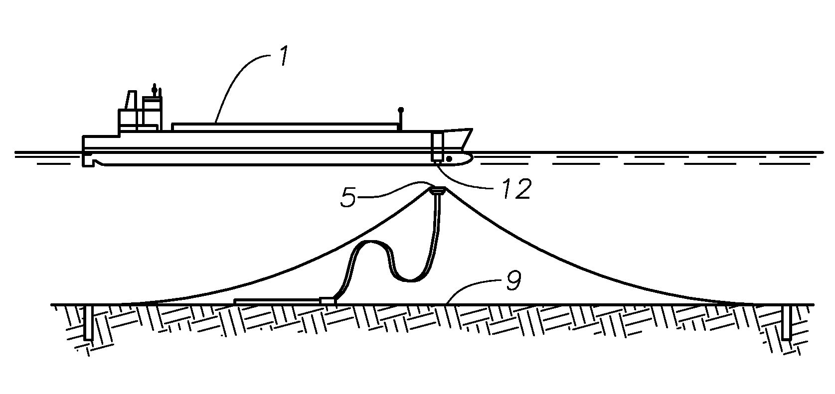
Detachable mooring and fluid transfer system

a technology of fluid transfer system and mooring system, which is applied in the direction of waterborne vessels, special-purpose vessels, buoys, etc., can solve the problems of large and expensive towers, large drag and energy losses on those disconnectable, and mandated expensive vessel construction

Active Publication Date: 2008-07-10
SOFEC
View PDF50 Cites 31 Cited by
  • Summary
  • Abstract
  • Description
  • Claims
  • Application Information

AI Technical Summary

Benefits of technology

[0021]Another object of the invention is to provide a mooring system that requires a significantly smaller opening in the vessel that includes the capability to plug the opening so that a virtually smooth ship bottom is achieved at t

Problems solved by technology

Turrets are generally large and expensive structures that usually include large diameter upper and lower bearings.
Such structure mandates expensive vessel construction.
Furthermore, large openings in the vessel hull to accommodate mooring buoys cause significant drag and energy losses on

Method used


Image

  • Detachable mooring and fluid transfer system
  • Detachable mooring and fluid transfer system
  • Detachable mooring and fluid transfer system

Examples


second embodiment

[0071]FIG. 11 shows a side view in partial cross section of a mooring and fluid transfer system 102 of the invention. The system 102 of FIG. 11 is substantially identical to the system 100 of FIG. 8A except that the collet segments are pushed inwardly for connection and outwardly for disconnection. Movable connector sleeve 189 is coaxially disposed outside of housing 192 rather than being disposed coaxially within housing 192, as shown in FIG. 8A.

[0072]FIG. 12 illustrates the mooring and fluid transfer system 100 of FIG. 8A equipped with optional metal-to-metal contact shoes 110 disposed between the top of the buoy 155 and the bottom of vessel 157. The contact shoes 110 increase the diameter of the load path between buoy 155 and vessel 157, thereby reducing the pull-in load requirements and the effective load on structural connector 156. The metal-to-metal contact interface allows structural connector 156 to develop external structural preload between buoy 155 and vessel 157. This p...

third embodiment

[0073]FIG. 13 shows a side view in partial cross section of one half of a mooring and fluid transfer system 106 according to the invention. The system 106 of FIG. 13 is similar to the system 100 of FIG. 8A except that the buoy is formed of two individual sections: an upper buoy 164 and a lower buoy / chain table 165. Axial / radial bearing 154 rotatively connects upper buoy 164 to lower buoy / chain table 165 to allow the upper buoy 164 and vessel 157 to weathervane. This arrangement allows the chain table anchor leg attachment points or ears 149A to be placed about a larger diameter, thereby increasing the yaw stiffness of the mooring system. The arrangement of FIG. 13 also allows anchor leg connection 153 to be closer in elevation to bearing assembly 154, and bearing assembly 154 to be closer in elevation to structural connector 156, thus reducing the moment loading on bearing assembly 154 and structural connector 156. Like the embodiment of FIG. 12, the bottom of the vessel includes op...


PUM


Abstract

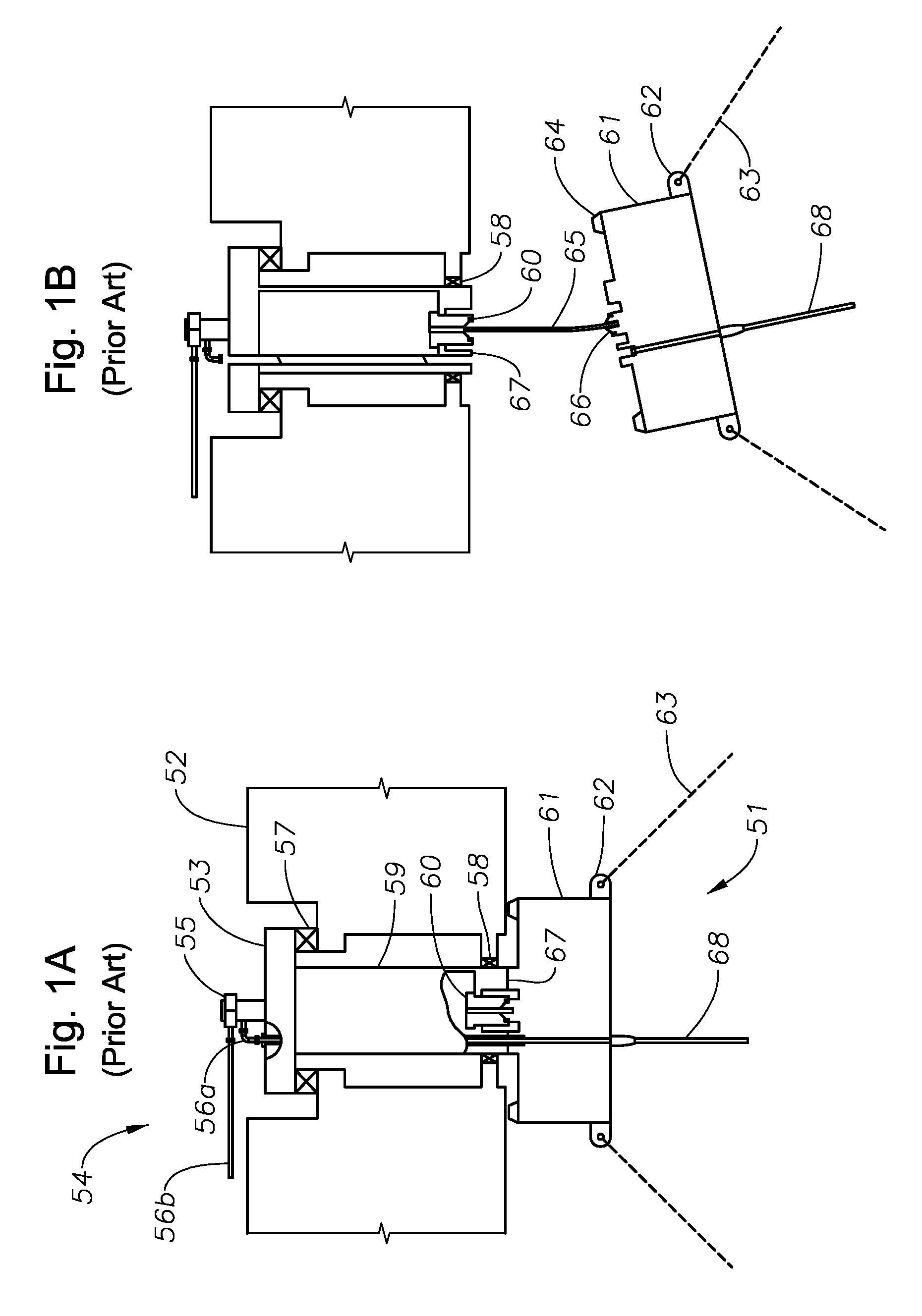
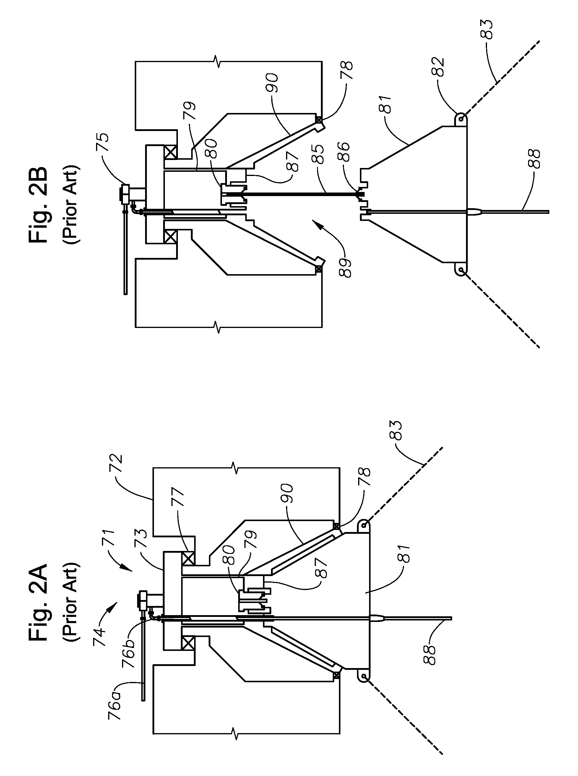
A mooring system comprising a submerged buoy releasably connected to a vessel adjacent its keel by a structural connector. The structural connector consists of a cylindrical sleeve coaxially movable with respect to a cylindrical housing by circumferential actuators. The lower ends of the connector sleeve and connector housing capture a number of collet segments circumpositioned therebetween that radially pivot in and out as the connector sleeve is moved axially within the connector housing. The lower ends of the collet segments extend downward to a connector hub on the buoy and releasably engage a groove therein, dogging the bearing hub against the vessel. A combined bearing assembly that supports both axial and radial loading revolvably connects the buoy to a moored chain table.

Description

CROSS REFERENCE TO RELATED APPLICATION[0001]This application claims priority from Provisional Application 60 / 878,954 filed Jan. 5, 2007.BACKGROUND OF THE INVENTION[0002]1. Field of the Invention[0003]This invention concerns detachable mooring systems for loading and offloading liquid petroleum product oil tankers, floating storage (FSO) vessels, floating production storage and offloading (FPSO) systems, floating vessels for natural gas offloading (for example, a cryogenic liquefied natural gas (LNG) regas import terminal), and LNG transport vessels.[0004]2. Description of the Prior Art[0005]Numerous patents are known that pertain to disconnectable mooring systems, most of which utilize a submerged buoy that can be detachably released from a floating vessel. For example, U.S. Pat. No. 5,651,708 issued to Borseth shows a detachable buoy with a geostationary part. The Borseth buoy has an outer body that is received in a recess in the bottom of the vessel, where the outer body is fixed ...

Claims


Application Information

Patent Timeline
IPC IPC(8): B63B22/02
CPCB63B21/508B63B22/026B63B22/025B63B22/023
Inventor LINDBLADE, STEPHEN P.
Owner SOFEC
Learn More