Condensing device for dish-washing machine and dish-washing machine provided with condensing device

A condensing device and dishwasher technology, which is applied to household cleaning devices, tableware washing machines/rinsing machines, tableware washing machines/rinsing and washing machine parts, etc. Drying and other problems, to achieve the effect of improving condensation efficiency, speeding up airflow and reducing space occupation

Active Publication Date: 2017-04-05
QINGDAO HAIER DISHWASHER +1
View PDF7 Cites 15 Cited by
  • Summary
  • Abstract
  • Description
  • Claims
  • Application Information

AI Technical Summary

Problems solved by technology

[0002] The current existing dishwashers will generate a large amount of water vapor during the dishwashing stage, and the water vapor in the inner tank of the dishwasher is in a saturated state. In this state, it is not conducive to the drying of the tableware. If the tableware cannot be dried for a long time, bacteria may breed and other microorganisms, which is not conducive to the hygiene of tableware
[0003] There are many kinds of existing dishwasher condenser structures. The relatively simple device uses a micro-fan and a small-diameter hose to extract water vapor from the inner tank. The disadvantage of this device is that it is low in efficiency. Under this condition, only a limited amount of water vapor can be extracted, and the effect is very limited.
The other is a device that uses a fan and an injection-molded cavity structure to act on the inner tank to form a circulation path to condense water vapor, such as the dishwasher drying device disclosed in Patent No. 201120027697. The fan is installed on the top of the inner tank to condense water vapor. The device is flat, the air inlet of the fan is connected with the inner container, the exhaust port of the fan is connected with the condensation channel, the bottom of the condensation channel is connected with the inner container through the drain port, and the water vapor in the inner container is blown from the top by the fan. The air inlet enters the condensation channel, and the condensed gas and condensed water enter the inner tank from the drain outlet below to form an air circulation flow. This device has the problems of long condensation time, loud fan noise, and low condensation efficiency.

Method used


Image

  • Condensing device for dish-washing machine and dish-washing machine provided with condensing device
  • Condensing device for dish-washing machine and dish-washing machine provided with condensing device
  • Condensing device for dish-washing machine and dish-washing machine provided with condensing device

Examples


Embodiment 1

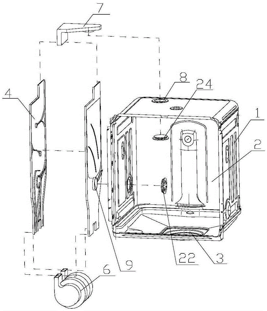
[0034] Such as figure 2 with image 3 As shown, in the present embodiment, the condensing device 4 includes a condenser 5, a blower fan 6 and an air intake passage 7, the top of the condenser 5 communicates with the air intake passage 7, and an air inlet 8 is provided on the top wall of the inner container 2, The air intake channel 7 is connected with the air intake port 8, and the water vapor in the liner 1 enters the air intake channel 7 through the air intake port 8, and finally enters the condenser 5, where the water vapor is condensed. The bottom of the condenser 5 is connected with the blower fan 6, and the blower fan 6 is installed between the bottom wall of the inner container 1 and the shell bottom wall of the dishwasher, so the inner container 1 and the shell of the dishwasher can be used to isolate noise to the greatest extent.

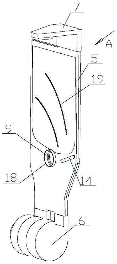
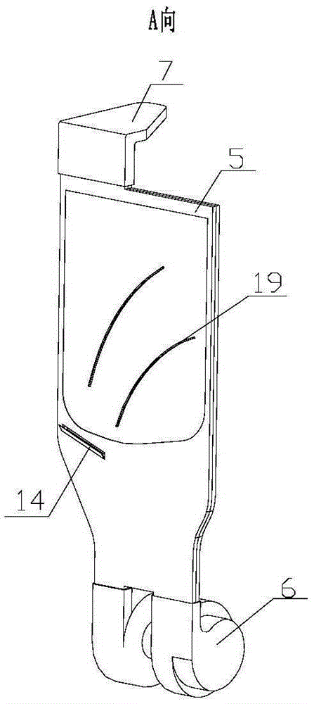
[0035] Such as Figure 2 to Figure 4 As shown, the condenser 5 is flat and formed by interlocking two side plates 5a and 5b, and the ch...

Embodiment 2

[0054] The difference from Embodiment 1 is that two fans 6 are used. The air outlet of one fan 6 is connected to the inlet of the air supply channel 12 in the condenser 5 to provide power for the internal air circulation, and the exhaust of the other fan 6 The outlet is connected to the inlet of the cooling air channel 11 in the condenser 5, which provides power for the external air circulation. There is also a return air port on the fan 6 which provides power for the internal air circulation, and is connected with the outlet of the condensation channel 13 in the condenser 5. A drain port 23 is provided at the bottom of the fan 6 for discharging a small amount of condensed water entering the fan 6 .

[0055] Both fans 6 are installed between the bottom wall of the liner 1 and the bottom wall of the shell.

Embodiment 3

[0057] The difference from Embodiment 1 and Embodiment 2 is that two fans 6 are used, and there are two airflow passages in the condenser 5, one of which is the air supply passage 12 for delivering airflow to the inner tank 1, and the air supply passage 12 The side plate 5b of the condenser 5 of 12 is provided with an air supply port 9, which communicates with the inner tank 1; the other is a condensation channel 13, and the water vapor in the inner tank 1 enters the air intake channel 7 from the air inlet 8 at the top of the inner tank 1 Finally, it enters the condensation channel 13 of the condenser 5 , and the water vapor is condensed in the condensation channel 13 . One of the fans 6 has an air exhaust port and an air return port, the air exhaust port is connected with the inlet of the air supply channel 12, and provides power for the internal air circulation, and the air return port is connected with the outlet of the condensing channel 13 of the condenser 5, in this fan ...


PUM


Abstract

The invention relates to a condensing device for a dish-washing machine and the dish-washing machine provided with the condensing device. The condensing device comprises an inner container, a condenser and draught fans. One end of the condenser communicates with the inner container through an air inlet, and the other end of the condenser is connected with the draught fans. An air supply opening communicating with the inner container is formed in one side plate of the condenser. Airflow is conveyed into the condenser and supplied into the inner container through the air supply opening so that water vapor can enter the condenser through the air inlet to form inner airflow circulation, meanwhile, cooling airflow is conveyed to the outer surface of the condenser to form outer airflow circulation, and power is provided for inner airflow circulation and outer airflow circulation through the two draught fans correspondingly or through one draught fan at the same time. The condensing device has inner airflow circulation and outer airflow circulation at the same time, the flowing speed of airflow on the outer surfaces of the side plates of the condenser can be increased, the surface temperature of the condenser can be reduced, fast condensation of the water vapor in the condenser can be facilitated, and the condensation efficiency can be greatly improved.

Description

technical field [0001] The invention relates to a dishwasher, in particular to a condensing device for a dishwasher, which belongs to the technical field of household appliances. Background technique [0002] The current existing dishwashers will generate a large amount of water vapor during the dishwashing stage, and the water vapor in the inner tank of the dishwasher is in a saturated state. In this state, it is not conducive to the drying of the tableware. If the tableware cannot be dried for a long time, bacteria may breed and other microorganisms, which is not conducive to the hygiene of tableware. [0003] There are many kinds of existing dishwasher condenser structures. The relatively simple device uses a micro-fan and a small-diameter hose to extract water vapor from the inner tank. The disadvantage of this device is that it is low in efficiency. Under this condition, only a limited amount of water vapor can be extracted, and the effect is very limited. The other i...

Claims


Application Information

Patent Timeline
Patent Type & Authority Applications(China)
IPC IPC(8): A47L15/42A47L15/48
CPCA47L15/483
Inventor 姜战存潘显杰王文龙
Owner QINGDAO HAIER DISHWASHER
Why Eureka
Try Eureka