Continuous drying system for slurry or powder and its working method

A drying system and drying technology, which is applied to the dryer of static materials, the separation method, and the drying of solid materials, etc., can solve the problems of high water content of materials, low production efficiency, and low heat transfer efficiency, and achieve high evaporation efficiency and production efficiency. The effect of high efficiency and high recovery rate

Active Publication Date: 2017-03-15
邹岳明
View PDF10 Cites 4 Cited by
  • Summary
  • Abstract
  • Description
  • Claims
  • Application Information

AI Technical Summary

Problems solved by technology

The disadvantage of this prior art is that it needs to be stopped for loading and unloading, and continuous work cannot be realized, resulting in low production efficiency
The disadvantage of this prior art is that: the multi-layer annular cavity is set up and down, and for the material with high consistency, it is easy to block the blanking channel; for the slurry with too much water, the material will quickly flow from the top annular cavity The liquid flows into the bottom annular cavity, which makes it impossible to dry the material; secondly, each annular cavity is heated unevenly, the temperature of the annular cavity at the bottom is higher, and the temperature of the annular cavity at the top is lower
This makes it difficult to control the drying temperature, that is, if the temperature of the annular cavity at the bottom is controlled too high, it will easily lead to carbonization of the material; if the temperature of the annular cavity at the bottom is not enough, the moisture content of the material will be too high, that is, the drying will not meet the standard
Secondly, the material needs to be sent to the feed port on the annular cavity on the top floor. For materials with poor fluidity or high consistency, pumps cannot be used to transport them, resulting in difficulty in feeding. The feeding is mainly done manually, which is time-consuming and labor-intensive.
Thirdly, the agglomeration layer is easy to appear on the bottom wall of each annular cavity, and it is difficult to clean it. At the same time, the agglomeration layer leads to a significant decrease in the heat transfer efficiency between the annular cavities, which seriously affects the drying effect

Method used


Image

  • Continuous drying system for slurry or powder and its working method
  • Continuous drying system for slurry or powder and its working method
  • Continuous drying system for slurry or powder and its working method

Examples


Embodiment 1

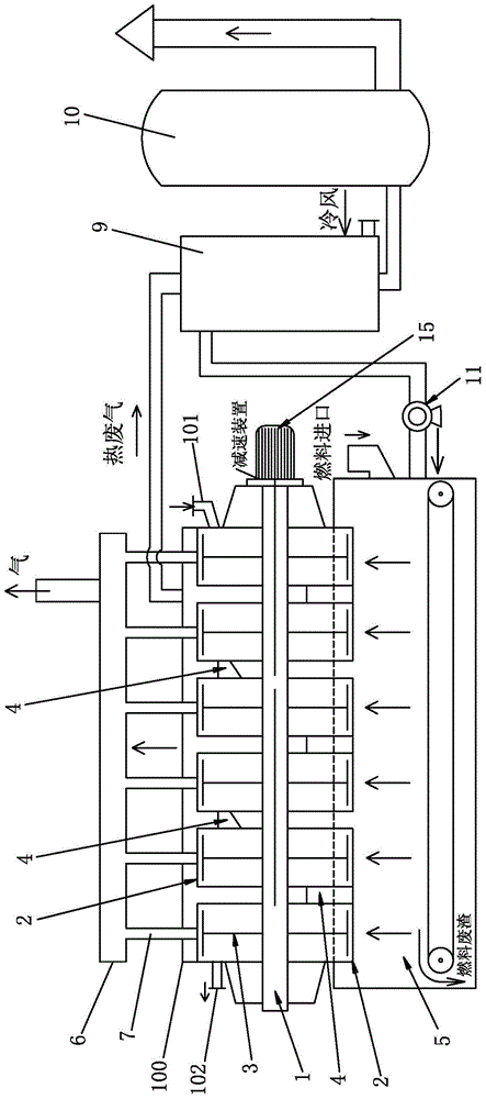
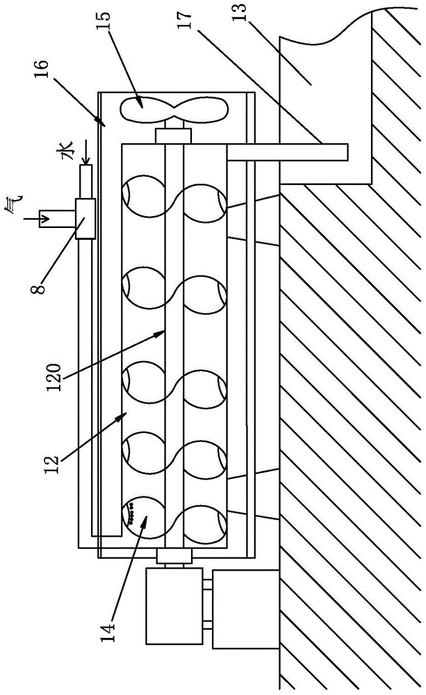
[0035] See figure 1 The continuous drying system for slurry or powder in this embodiment includes: a drying host 100 and a collection system for collecting volatiles discharged from the drying host 100 .

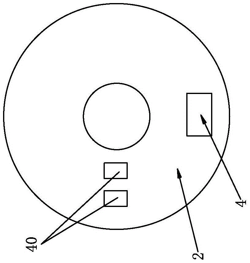
[0036] The drying host 100 includes: a central main shaft 1, 5 to 10 annular cavities 2 arranged in parallel vertically, and a heating device for heating each annular cavity 2 . The annular cavities 2 are arranged alternately front and back and are fitted in a sliding seal on the central main shaft 1, and the scrapers 3 in each annular cavity are fixed on the central main shaft 1 for driving each scraper to rotate. The scraper 3 is in the shape of a rice pad or wind blades, and is attached to the rear side wall of the corresponding annular cavity. The scraper 3 is adapted to rotate against the rear side wall of the annular cavity 2, so as to prevent the formation of a scale layer on the bottom plate, which affects the thermal conductivity of the bottom plate, and at the sam...

Embodiment 2

[0049] The working method of the continuous drying system of the slurry or powder described in the above-mentioned embodiment 1, comprising:

[0050] A. To heat each annular cavity 2; so that the temperature of the annular cavity 2 is suitable to reach 50-700°C (the specific temperature needs to be selected according to different materials).

[0051] B. Input the slurry through the pump or the powder through the screw conveyor from the feed port of the annular cavity at the front end, and at the same time turn on the main motor 15 to drive the central main shaft 1 to rotate, and at the same time, each scraper 3 rotates ;

[0052] C. Under the rotation of each scraper plate 3, the slurry or powder enters each annular cavity 2 for heat exchange and drying, and finally is discharged from the outlet of the rear annular cavity 2; during this period, the volatile matter is discharged from the The exhaust channel 6 is output, and the volatile matter is collected through a collection...


PUM


Abstract

The invention relates to a continuous drying system of slurry or powder. The continuous drying system comprises a drying host; the drying host comprises a plurality of closed cavities that are arranged vertically and arrayed at intervals front and back, and a heating device heating the cavities; the cavities are internally provided with material scraping plates suitable for rotation; the adjacent cavities are in sealing connection with each other by at least one material passing channel; at least one pair of adjacent cavities exists; inlets of the material passing channels formed between the adjacent cavities are positioned at the middle parts and / or the middle upper parts and / or the tops of the cavities in the height direction; an exhaust channel is arranged on at least one cavity; a material inlet is formed at the cavity at the front end; a material outlet is formed at the cavity at the rear end; and during working, under rotational action of the various material scraping plates, the slurry or the powder moves from the cavity at the front end to the cavity at the rear end sequentially. The continuous drying system can be applied to evaporation collection of phosphorus in phosphorus mud and phosphorus slag, residual liquid treatment of calcium oxide or calcium chloride and benzoyl chloride, drying of finished chemicals, comprehensive recovery processing of the three wastes, etc.

Description

technical field [0001] The invention relates to a continuous drying system for slurry or powder and its working method, which can be applied to the evaporation and collection of phosphorus in phosphorus sludge and slag, and the treatment of chemical residues such as calcium oxide or calcium chloride, benzoyl chloride, etc. , drying of chemical products, comprehensive recycling of three wastes, recovery of gasoline, diesel or engine oil, or organic chemical raw materials. Background technique [0002] In the prior art, the production of yellow phosphorus by the electric furnace method will produce wastes such as phosphorus sludge and phosphorus slag, and a considerable part of the yellow phosphorus in the discarded phosphorus sludge and phosphorus slag has not been completely refined, which causes a waste of resources. [0003] Existing methods for recovering yellow phosphorus include steam filtration, dry steaming, chemical reagent reaction, etc.; the steam filtration method...

Claims


Application Information

Patent Timeline
Patent Type & Authority Patents(China)
IPC IPC(8): F26B11/10F26B23/06F26B25/02F26B25/08
CPCB01D1/0064B01D1/0082B01D1/18B01D1/30F26B9/06F26B17/00F26B17/008F26B17/20F26B17/205F26B21/004F26B23/00F26B23/06F26B25/00F26B25/006F26B25/04F26B25/06
Inventor 陈红英陈泽强张华邹岳明邹玉杰
Owner 邹岳明
Why Eureka
Try Eureka