Condensation type heat exchange plate and condensation type heat exchanger with same

A technology of condensing heat exchangers and heat exchange plates, which is applied in the field of condensing heat exchange, can solve the problems of low condensation rate, poor corrosion resistance, and poor stability of the main heat exchanger and condensing heat exchangers, and achieve enhanced heat exchange Thermal effect, strong sealing, rapid heating effect

Inactive Publication Date: 2014-08-27
CENT SOUTH UNIV
View PDF5 Cites 3 Cited by
  • Summary
  • Abstract
  • Description
  • Claims
  • Application Information

AI Technical Summary

Problems solved by technology

[0004] The technical problem solved by the present invention is to propose a new type of condensing heat exchange plate and its applied condensing heat exchanger, so as to solve the problems of low condensation rate and corrosion resistance of the main heat exchanger and condensing heat exchanger in wall-hung boilers. Poor capability, poor stability, high cost, etc.

Method used


Image

  • Condensation type heat exchange plate and condensation type heat exchanger with same
  • Condensation type heat exchange plate and condensation type heat exchanger with same
  • Condensation type heat exchange plate and condensation type heat exchanger with same

Examples


Embodiment 1

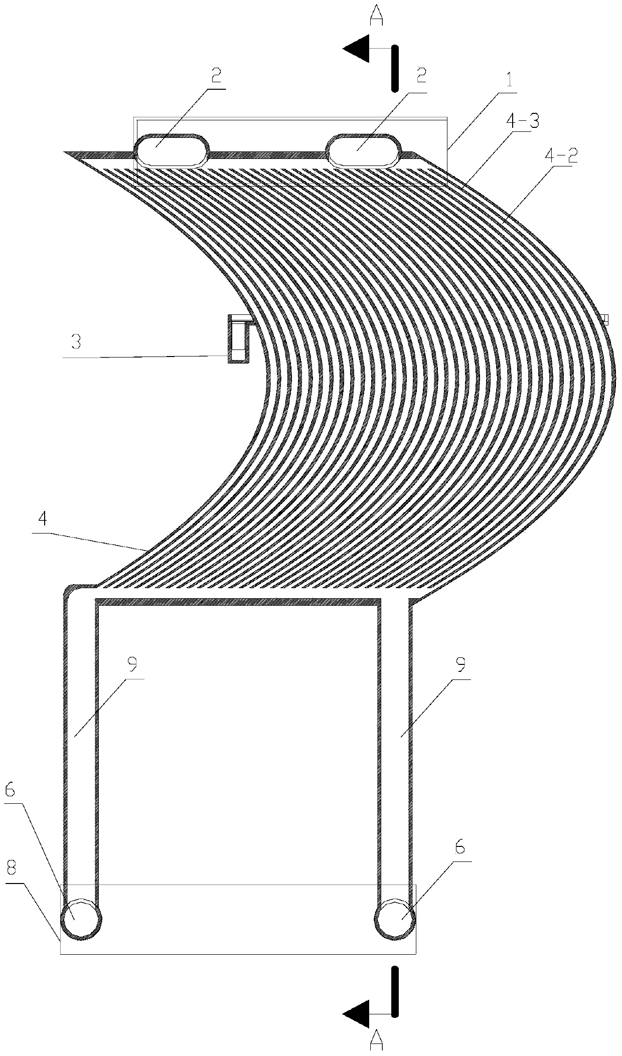
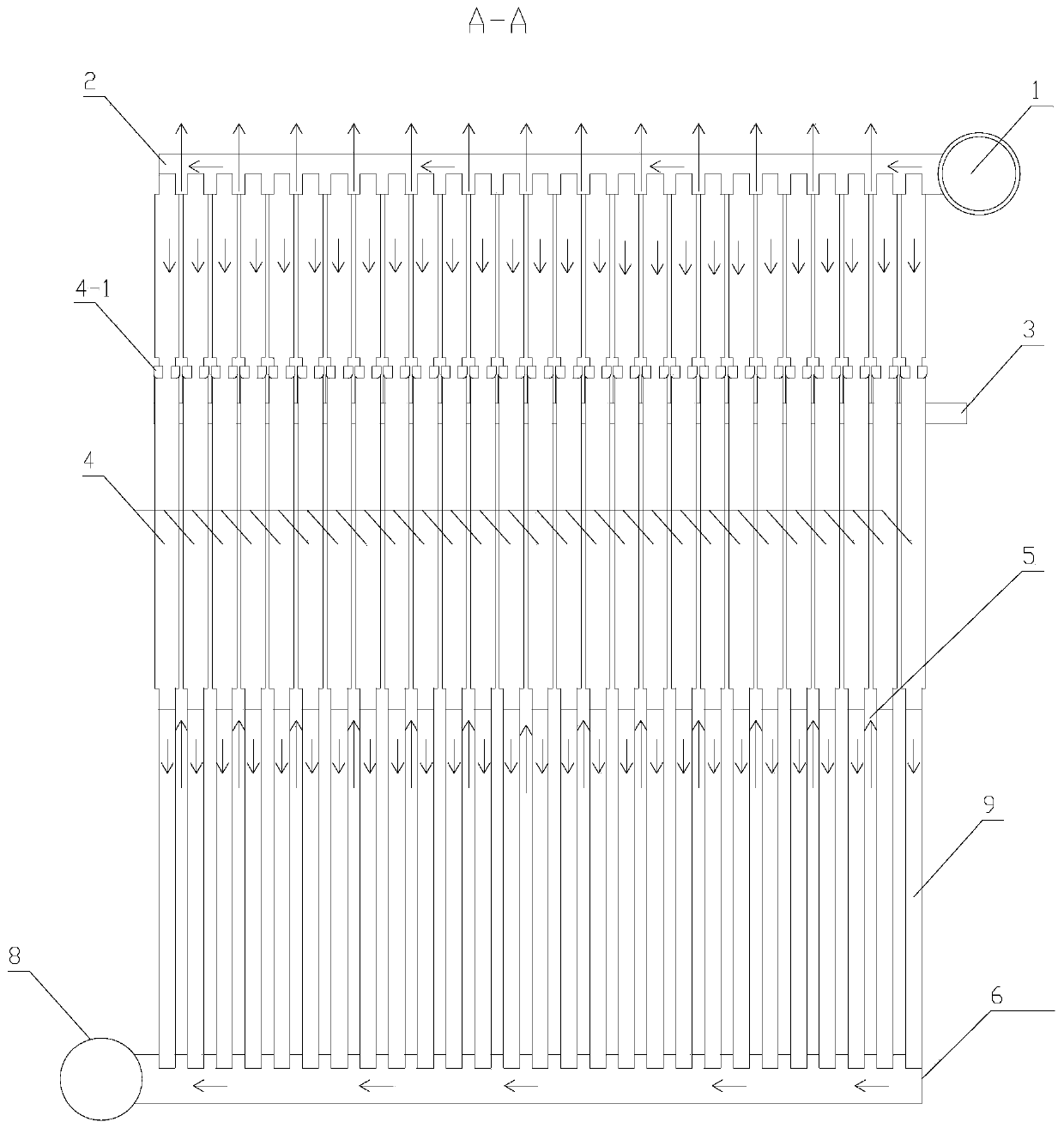
[0026] see Figure 4 to Figure 7 The interior of the heat exchange plate 4 is separated by a partition plate 4-3 to form a number of parallel arc-shaped water passages 4-2, and the upper and lower ends of the heat exchange plate 4 are respectively provided with connecting pipes connected to the water inlet pipe and the water outlet pipe. Port 4-5, the position of the connecting port 4-5 is provided with a water hole 4-6, and the two ends of the inner cavity of the heat exchange plate connected by the water hole 4-6 are respectively provided with a water collection space 4-8 and all water passages The channels are connected; both sides of the heat exchange plate 4 are provided with fins 4-4.

[0027] For details, see Figure 4 , the fins 4-4 are arc-shaped fins with the same shape as the partition plate 4-3 inside the heat exchange plate, and their positions correspond to the positions of the partition plates one by one.

[0028] see Figure 4 to Figure 6 Condensate water co...

Embodiment 2

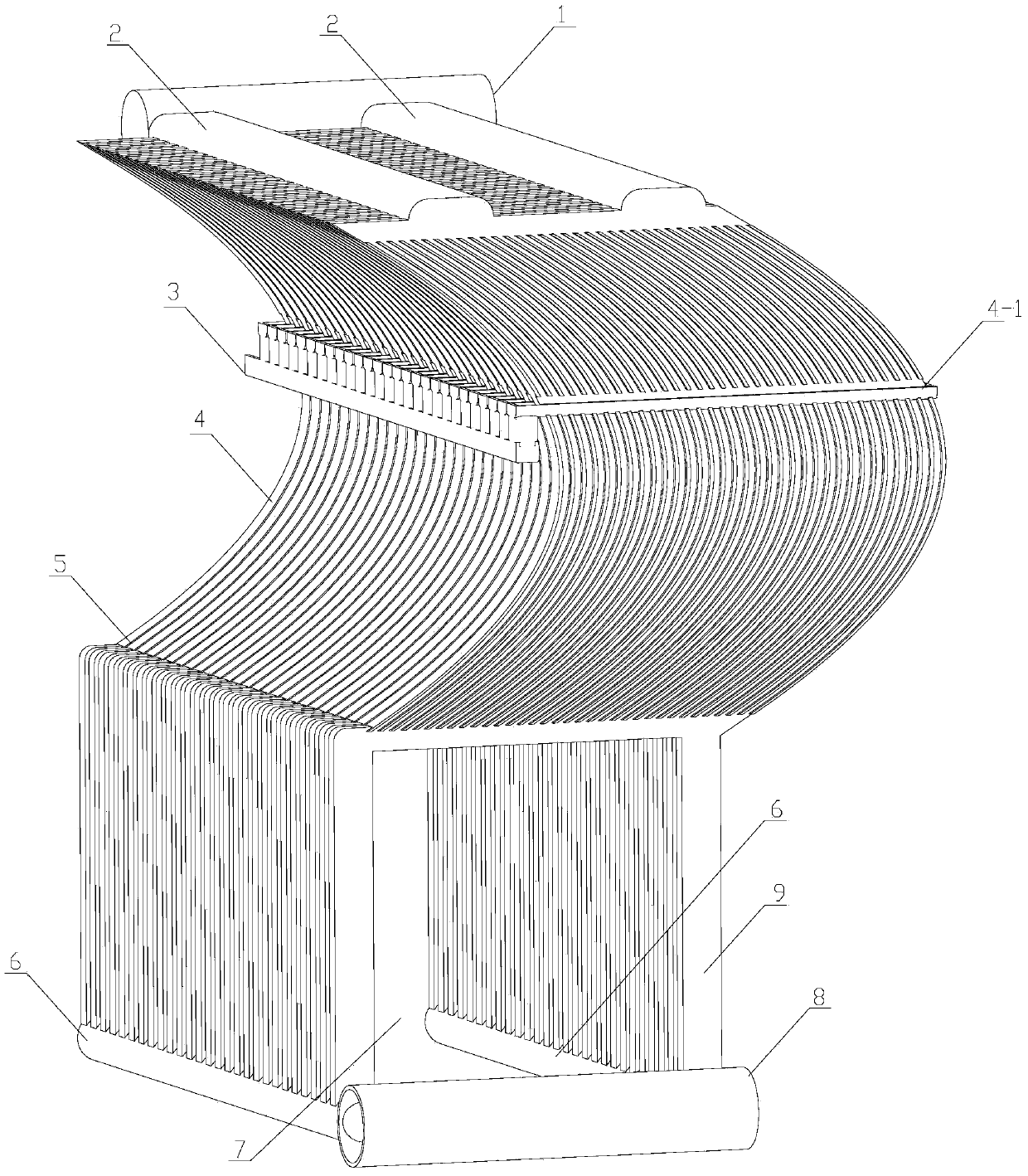
[0032] see in conjunction Figure 1 to Figure 3 , a condensing heat exchanger formed by combining the condensing heat exchange plates in Example 1 side by side, the flue gas pipeline of the condensing heat exchanger is surrounded by the fins 4-4 outside the adjacent heat exchange plates The gap between the plates is 5, and the water passage is the water passage 4-2 inside the heat exchange plate 4. There is a certain gap between the adjacent heat exchange plates 4, and the two sides of the entire heat exchanger are sealed with aluminum skins. Form an upward flue gas channel. The space enclosed by the downcomer 9 at the bottom of the heat exchange plate 4 is the combustion chamber 7, the top of the condensing heat exchanger is provided with a water inlet pipe 1 connected in parallel with the water hole at the top of the heat exchange plate 4, and the bottom is provided with an outlet pipe 8 It is connected in parallel with the water hole at the bottom of the heat exchange plat...


PUM


Abstract

The invention discloses a condensation type heat exchange plate and a condensation type heat exchanger with the condensation type heat exchange plate. The interior of the heat exchange plate is divided into a plurality of arc-shaped water flowing channels which are parallel to one another, pipe connecting ports which are connected with a water inlet pipe and a water outlet pipe respectively are formed in the upper end and the lower end of the interior of the heat exchange plate respectively, water holes are formed in the positions of the pipe connecting ports, the two ends, communicated with the water holes, of an inner cavity of the heat exchange plate are provided with water collecting spaces respectively, the water collecting spaces are communicated with all the water flowing channels, and fins are arranged on the two outer sides of the heat exchange plate respectively. The condensation type heat exchanger is formed by combining a plurality of heat exchange plates in parallel, a smoke pipeline of the condensation type heat exchanger is an inter-plate gap defined by the ribs outside every two adjacent heat exchange plates, the water flowing channels inside the heat exchange plates serve as water flowing pipelines of the condensation type heat exchanger, and the space defined by down pipes on the bottoms of the heat exchange plates serves as a combustion chamber. The condensation type heat exchange plate is made of cast aluminum alloy through die casting and has the advantages that the heat resistance is high, the sealing performance is high, and the balance among the corrosion resistance, the good head conductivity and the manufacturing technology is well considered, heat loss is effectively reduced, and heat exchange efficiency is improved.

Description

technical field [0001] The invention belongs to the technical field of condensation heat exchange, and in particular relates to a condensation heat exchange plate and a condensation heat exchanger applied thereto. Background technique [0002] The exhaust gas temperature of a traditional wall-hung boiler is generally around 180°C, which contains a large amount of water vapor. If the exhaust gas temperature is further reduced and the condensation heat of water vapor is recycled, the thermal efficiency of the wall-hung boiler will be significantly improved. Theory proves that its thermal efficiency can be as high as 111 % (Based on low calorific value). Therefore, the application of condensation technology was born. At the same time, the study found that when the flue gas is condensed, SOx and NOx in the flue gas can be almost completely dissolved in the condensed water, so that the harmful substances discharged into the atmosphere are greatly reduced. It can be seen that bo...

Claims


Application Information

Patent Timeline
Patent Type & Authority Applications(China)
IPC IPC(8): F28F3/08F24H9/00
Inventor 李德忠何娜萍刘志强
Owner CENT SOUTH UNIV
Why Eureka
Try Eureka