Gas-liquid separation type sleeve evaporator

A gas-liquid separation and evaporator technology, applied in evaporator/condenser, refrigeration and liquefaction, refrigeration components, etc., can solve the problems that the liquid phase cannot be effectively spread, complex gas-liquid two-phase flow, stratified flow is inevitable, etc. , to achieve the effects of saving materials, enhancing disturbance, and reducing production and operation costs

Inactive Publication Date: 2008-02-20
TSINGHUA UNIV
View PDF0 Cites 17 Cited by
  • Summary
  • Abstract
  • Description
  • Claims
  • Application Information

AI Technical Summary

Problems solved by technology

In the process of gasification heat transfer in the tube, although the heat transfer effect will be improved with the increase of the dryness, the increase is not large, and the gasification heat transfer in the tube is used, and the liquid phase cannot be effectively spread, forming a strong heat transfer effect. liquid film convective boiling state
At the same time, the horizontal helical tube structure is adopted. Although there is a disturbance of the secondary flow inside, the stratified flow is still inevitable.
Stratified flow will lead to partial dryness in the tube, and a large amount of liquid phase will accumulate in the bottom layer of the tube, which will greatly weaken the heat transfer effect
On the other hand, the process of evaporation and boiling in a single tube also leads to complex gas-liquid two-phase flow, which has a very adverse impact on system operation stability, flow resistance and system regulation.

Method used


Image

  • Gas-liquid separation type sleeve evaporator
  • Gas-liquid separation type sleeve evaporator
  • Gas-liquid separation type sleeve evaporator

Examples


Embodiment Construction

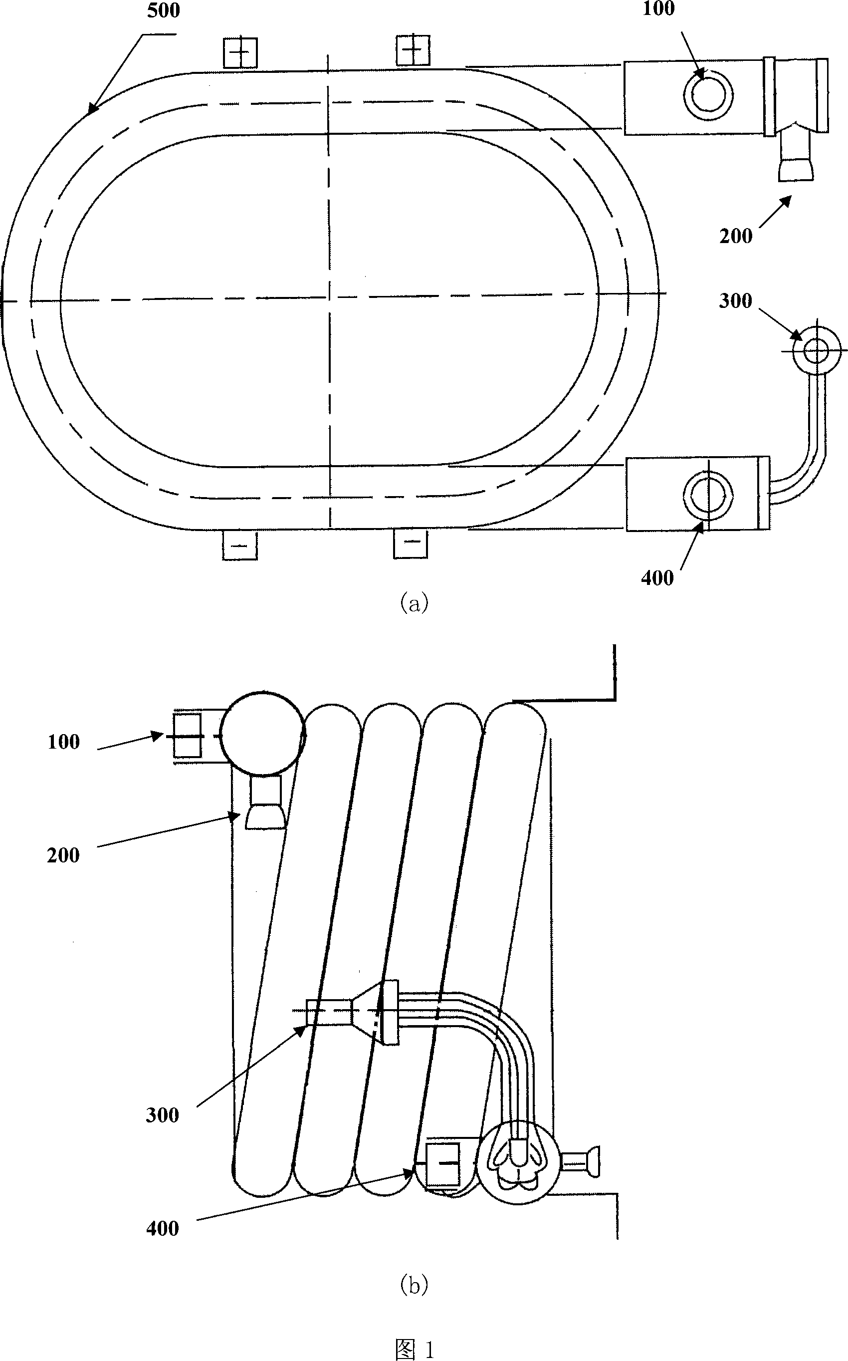
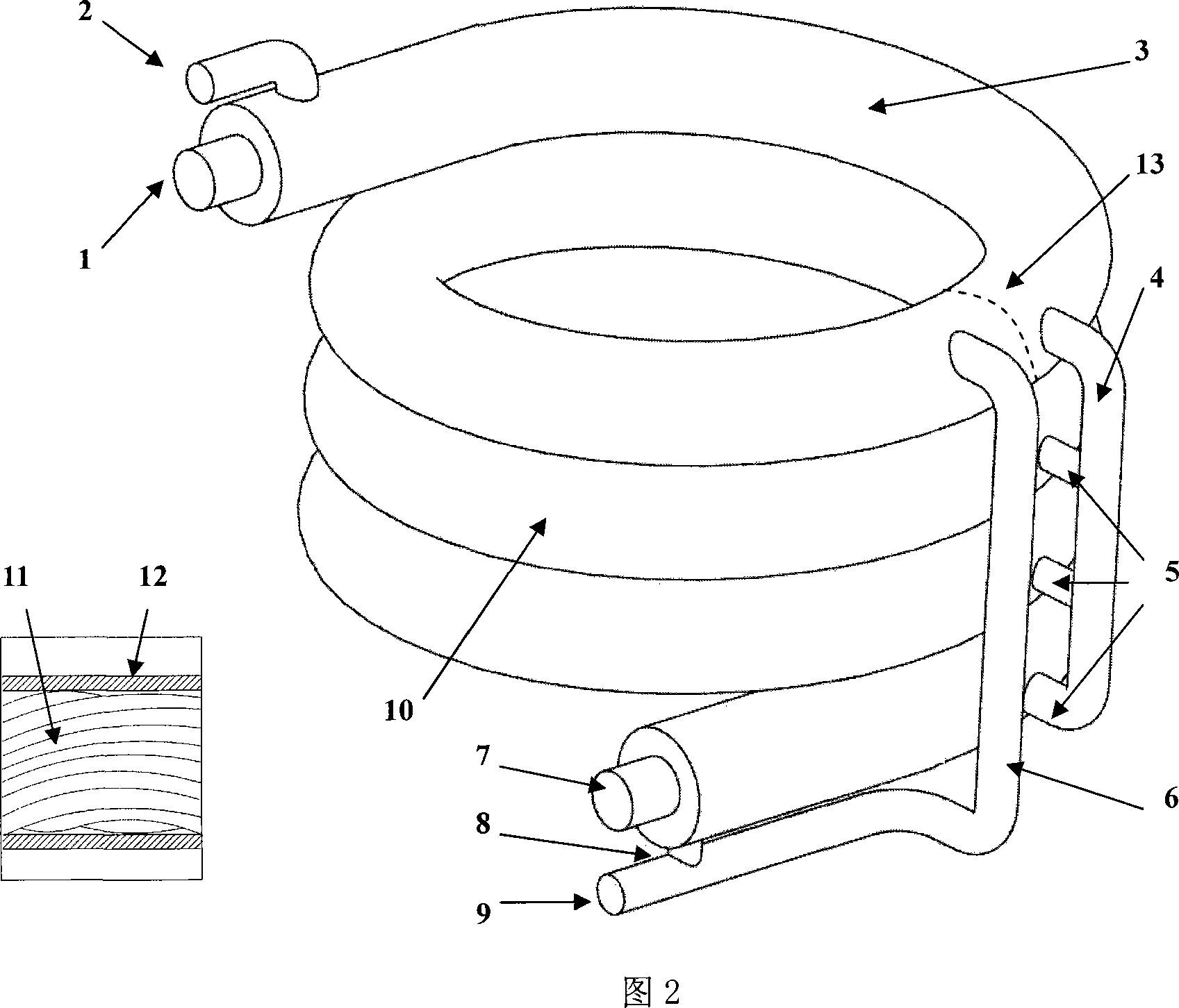
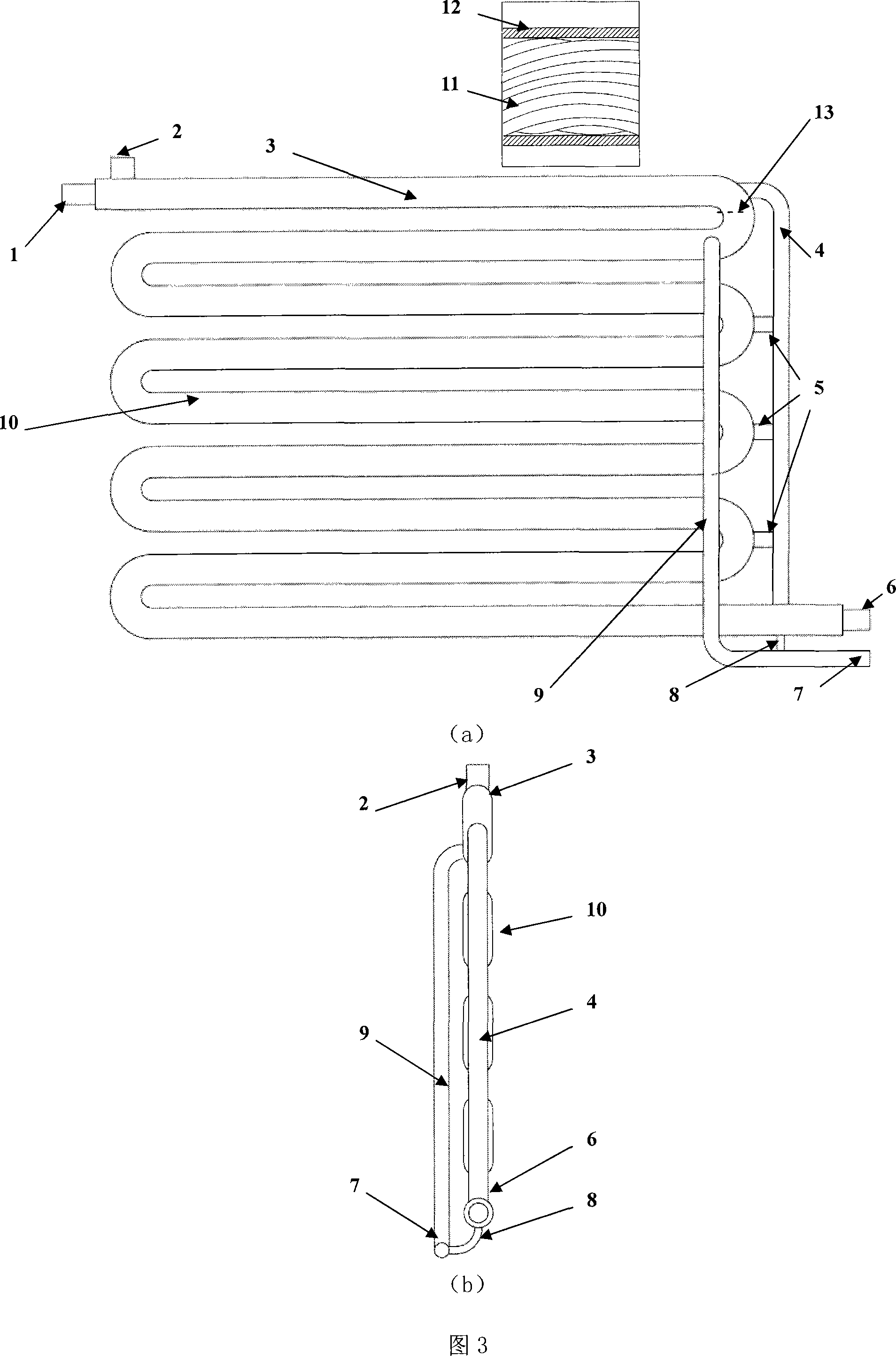
[0020] Further illustrate the present invention below in conjunction with accompanying drawing.

[0021]Fig. 2 is a schematic diagram of a spiral gas-liquid separation casing evaporator according to the present invention. Among them, 1. heating liquid (cooled liquid or water, the same below.) inlet, 2. evaporated liquid (or refrigerant, the same below.) steam outlet, 3. spiral superheating section, 4. gas collection and exhaust pipe, 5. Gathering exhaust port, 6. Evaporated liquid inlet pipe, 7. Heated liquid outlet, 8. Residual evaporated liquid liquid phase return port pipe, 9. Evaporated liquid inlet, 10. Spiral heat exchange section, 11. Twist the inner tube bundle, 12. the outer tube, 13. the separation device. In the helical casing evaporator, the outer casing (12) and several inner tubes (11) in which helically twist and distribute form the basic heat exchange part, and the whole is in a spiral shape. One end of the inner tube is the heating liquid inlet (1), and the ...


PUM


Abstract

The utility model relates to a gas-liquid separating bushing evaporator, belonging to the technical field of thermal equipment, which comprises an outer sleeve tube (12) and a plurality of torsion inner tube bundles (11) helically distributed in the outer sleeve tube as the basic heat exchanging part. One end of the inner pipe is an inlet (1) for heating liquid , while the other end is an outlet for heating liquid; the inlet (9) for evaporated liquid is arranged at the bottom of the spiral outer sleeve tube (12), and connected with a liquid phase return pipe (8) for residual evaporated liquid; a gas-collecting exhaust port (5) is communicated with a gas-collecting exhaust pipe (4) at the same location of each layer of spiral jacket; the exhaust port (5) is arranged at the upper reach of the interface of the evaporated liquid inlet (6) and the outer sleeve tube (12) to divide the whole heat exchanging part into a spiral heat exchanging section (10) and a spiral overheating section (3). The utility model also comprises a vertical type S-shaped gas-liquid separating casing evaporator. The utility model has the advantages of simple processing, better overall performance of bushing evaporative heat exchanger, less costs of the manufacture and operation of the evaporator.

Description

technical field [0001] The invention relates to a gas-liquid separation casing evaporator, which belongs to the technical field of thermal equipment. Background technique [0002] The casing evaporator is a kind of thermal equipment, which is widely used in power, chemical industry, air-conditioning engineering and refrigeration engineering, such as refrigerators, freezers, air-conditioning systems, chemical and petrochemical process evaporators, etc. [0003] Figure 1 shows a conventional casing evaporator, which consists of a concentric inner tube and an outer tube. As shown in Figure 1, Figure (a) is a top view of a traditional sleeve-type evaporator; Figure (b) is a side view of a traditional sleeve-type evaporator. Among them, 100-heat source liquid (cooled liquid or water) inlet, 200-evaporated liquid (refrigerant for air conditioning and refrigeration system) vapor outlet, 300-evaporated fluid inlet, 400-cooled liquid outlet, 500-outer sleeve . In order to save spa...

Claims


Application Information

Patent Timeline
Patent Type & Authority Applications(China)
IPC IPC(8): F25B39/02
Inventor 彭晓峰吴迪陆规张扬
Owner TSINGHUA UNIV
Why Eureka
Try Eureka