Cushion adjustable and display devices for treadmills

a display device and adjustable technology, applied in the field of treadmills, can solve the problems of not being able to adjust according to the needs of different users, and not being able to effectively provide a satisfied

Inactive Publication Date: 2008-07-17
CHANG DICK
View PDF3 Cites 32 Cited by
  • Summary
  • Abstract
  • Description
  • Claims
  • Application Information

AI Technical Summary

Benefits of technology

[0007]The present invention will become more obvious from the following description when taken in connection with the accompanying drawings which show, for purposes of illustration only, a preferred embodiment in accordance with the present invention.

Problems solved by technology

However, the resilient members 412 cannot effectively provide a satisfied result to the users and cannot be adjustable according needs of different users.

Method used


Image

  • Cushion adjustable and display devices for treadmills
  • Cushion adjustable and display devices for treadmills
  • Cushion adjustable and display devices for treadmills

Examples


Embodiment Construction

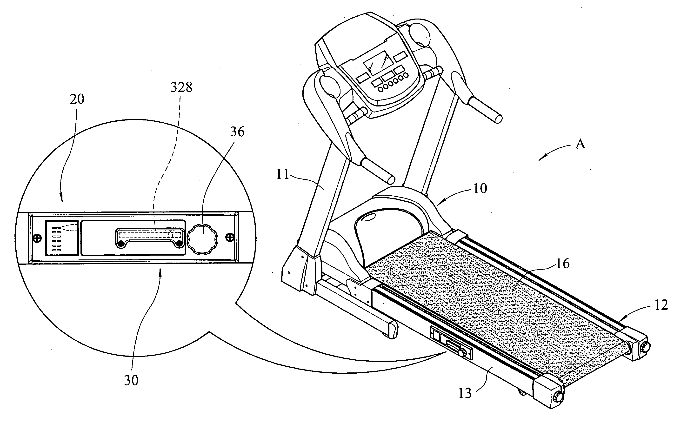
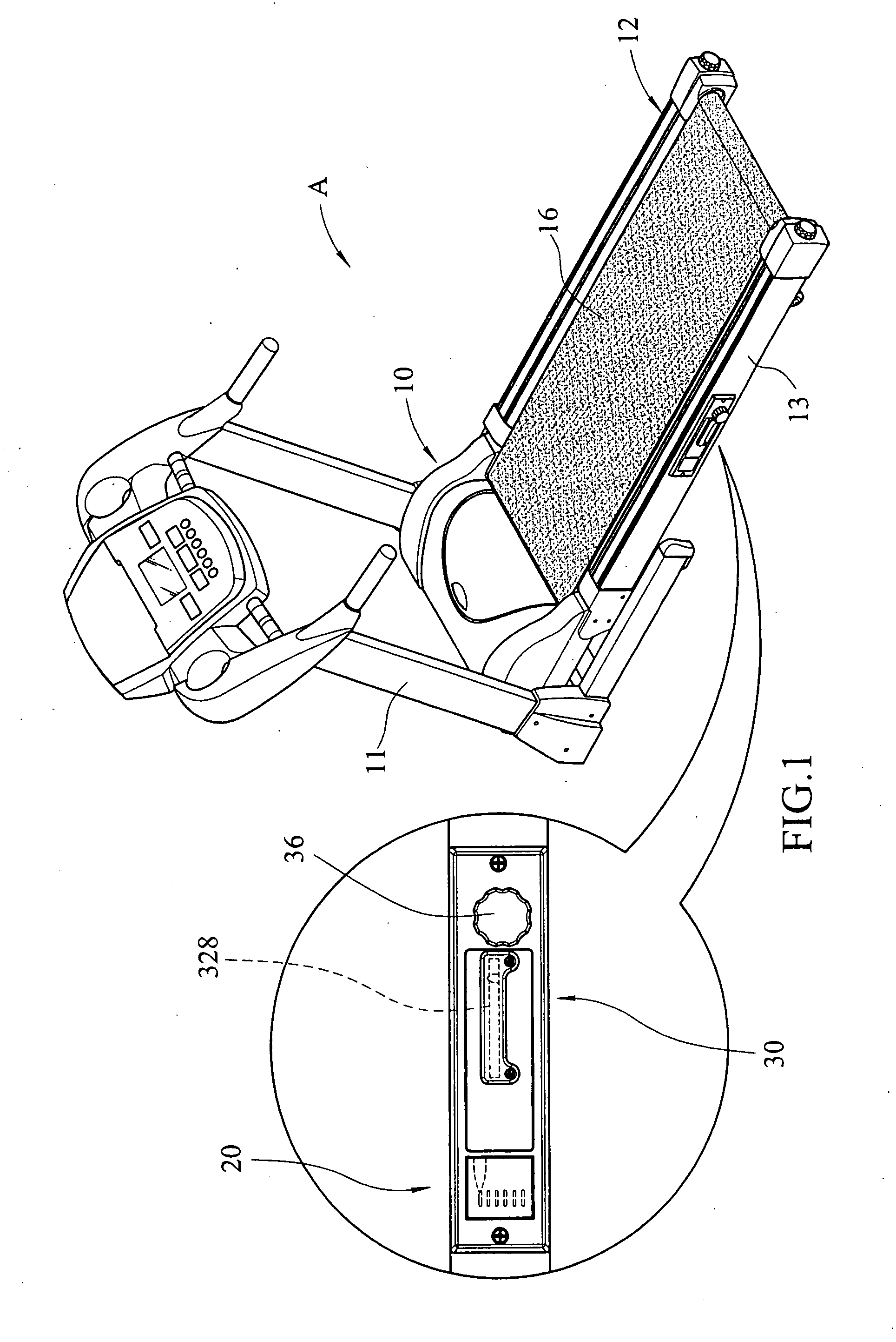
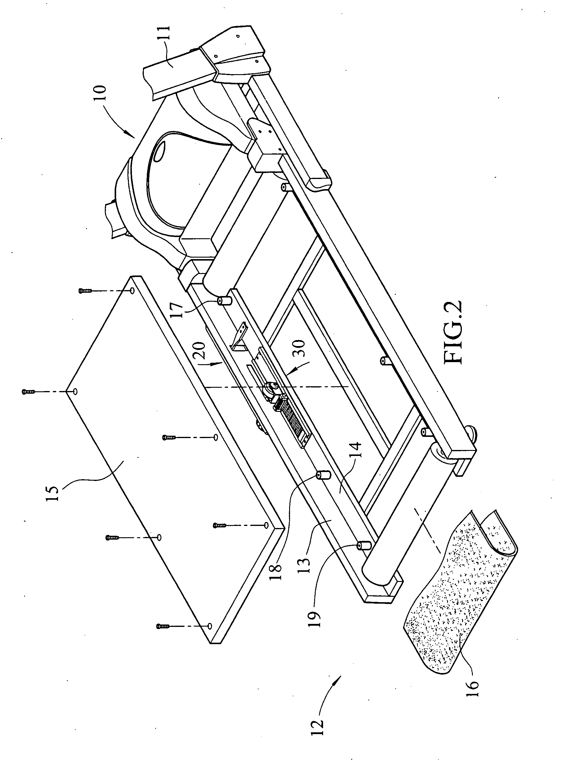
[0018]Referring to FIGS. 1 to 6, the treadmill “A” of the present invention comprises a frame 12 having two sides and a motor 10 and two rollers are connected between the two sides. Two rollers are driven by the motor 10. Two posts 11 extend from the two sides of the frame 12 and are connected with a handle. Each of the two sides of the frame 12 has a vertical portion 13 and a horizontal portion 14 which extends from an inner side of the vertical portion 13. A plurality of resilient members 17, 18, 19 are fixed on each of the two horizontal portions 14. A deck 15 is supported on the resilient members 17, 18, 19 and is fixed to the horizontal portions 14 by extending bolts through the deck 15, the resilient members 17 to 19 and being connected to the horizontal portions 14. A loop-like endless belt 16 is driven by the two rollers and the deck 15 is located between a top portion and a bottom portion of the loop-like endless belt 16.

[0019]A cushion display device 20 has an indication m...


PUM


Abstract

A cushion adjustable device for a treadmill includes a base plate fixed on a horizontal portion of one of two sides of a frame of the treadmill and a movable member is slidably engaged with a groove defined in the base plate. The movable member includes a resilient roller which is in contact with an underside of the deck of the treadmill. By moving the adjustable device, the resilient roller is moved to a desired position relative to the deck so as to provide a better cushion feature of the deck. A cushion display device includes an indication member and an extension rod which is fixed to the underside of the deck so that when the deck is deformed in vertical direction, the indication member is moved in vertical direction to show the deformation of the deck in the vertical direction.

Description

FIELD OF THE INVENTION[0001]The present invention relates to cushion adjustable and display devices for treadmills, wherein a resilient roller can be moved to a desired position under the deck so as to evenly support the load and the deformation of the deck can be displayed.BACKGROUND OF THE INVENTION[0002]A conventional treadmill 40 is shown in FIG. 9 and generally includes a frame with two side support boards 411 and two rollers 43 are connected between the two side support boards 411. A motor 41 is connected to a front end of the frame and two posts 42 extend from two sides of the frame so as to be connected with a handle which is not shown. A plurality of resilient members 412 are located on a top of each of the side support boards 411 and a deck 44 is supported on the resilient members 412 and fixed to the frame. An endless belt 45 is driven by the rollers 43 which are driven by the motor 41 and the deck 44 is located between the top portion and the bottom portion of the loop-l...

Claims


Application Information

Patent Timeline
Patent Type & Authority Applications(United States)
IPC IPC(8): A63B22/02
CPCA63B22/0235A63B2022/0228A63B2022/0207A63B22/0228A63B22/0207
Inventor CHANG, DICK
Owner CHANG DICK
Why Eureka
Try Eureka