
Eureka
For R&D, Eureka makes reading and utilizing patents & technical documents easy.
Eureka AIR
Designed for self-driven R&D workflows. Generate viable solutions, solve complex R&D challenges, empower your innovation with AI.

Eureka Materials
Designed for material experts only. Revolutionize your material R&D, from search, analyze, to developing new materials.

TechResearch
Generate reliable direction feasibility study reports for your R&D in just a few steps.

TechSeek
Discover and master advanced knowledge NOW. Basics, ideas, possibilities, all at once.

TechMind
As an expert in R&D Theories, TechMind can generates customized viable solutions instantly.

TechRisk
Analyze your overall solution with one click, know your potential R&D risks in advance.

TechMonitor
Get weekly tech updates, stay abreast of the latest tech innovations and key insights.
Adjustable Compression Staple and Method for Stapling with Adjustable Compression
- Summary
- Abstract
- Description
- Claims
- Application Information
AI Technical Summary
Benefits of technology
Problems solved by technology
Method used
Image

Examples
first embodiment
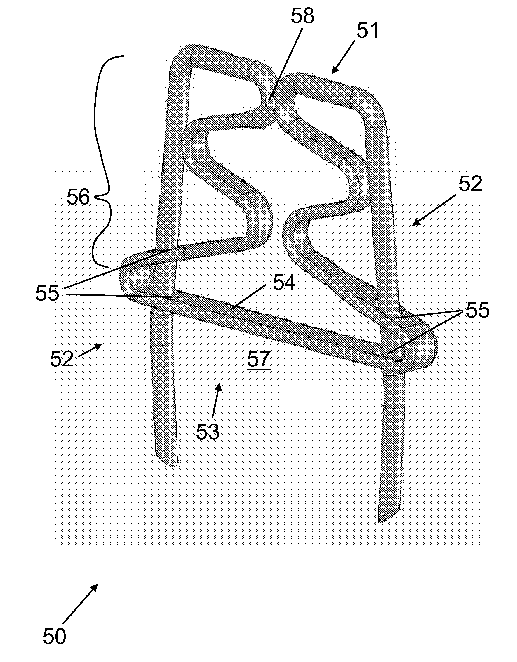
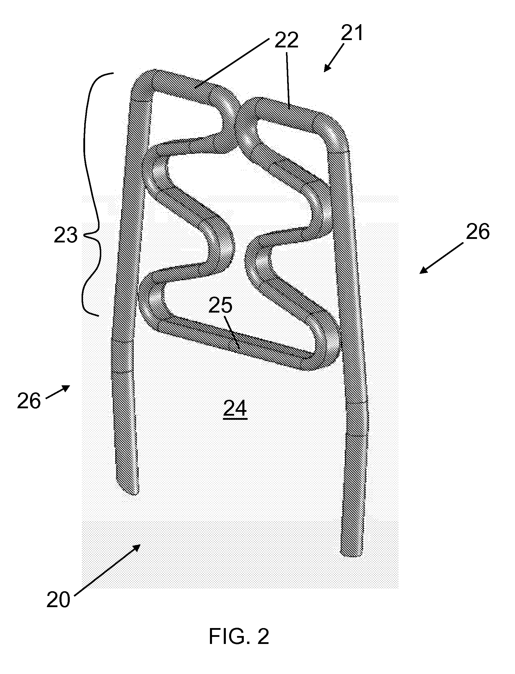
[0080]Referring now to the figures of the drawings in detail and first, particularly to FIG. 2 thereof, there is shown a first exemplary embodiment of an automatic optimal tissue compression (OTC) staple 20 according to the invention. In this first embodiment, the bridge 21 has a center bridge portion 22 and an extension 23 that substantially increases the overall length of the bridge 21—as compared to the bridge 2 of the staple 1 of FIG. 1. As the upper bridge portion 22 transitions into the extension 23, it curves into and within the central region 24 of the staple 20. This extension 23 can be in any shape or of any material so long as it delivers a pre-set compressive force to the tissue at a compressing portion 25, and as long as it allows for absorption (within the area between the compressing portion 25 and the upper bridge portion 22) of forces greater than this pre-set force. Therefore, the shape can be trapezoidal, triangular, sinusoidal, or any other configuration. An exem...
second embodiment
[0085]In this second embodiment, the OTC device 33 behaves similar to the OTC portions of the embodiment of FIG. 2 and can be shaped with the same variations of cross-section and other spatial characteristics and can be formed with the same variations in material composition. Variation of any attribute of the OTC device 33 allows for adjustment of the compressive and reactive force constants thereof on the compressed tissue. The extension 36 can be any shape or material so long as it delivers a pre-set compressive force to the tissue at the compressing portion 34 and as long as it allows for absorption of forces greater than this pre-set force. An exemplary embodiment selected for this exemplary OTC device 33 is a relatively sinusoidal set of curves traversing less than two periods. The extension 36 has two mirror-symmetrical portions each starting from the bridge 31 and ending at respective ends of the compressing portion 34. In this exemplary embodiment, neither the extension 36 n...
third embodiment
[0087]Notably different from the embodiments of FIGS. 2 and 3 is the compressing portion 44. Here, the width of the compressing portion 44 (defined along the line between the two legs 42 of the staple 40) is greater than the separation distance of the two legs 42. The compressing portion 44 is provided with ports 49 having a shape substantially corresponding to the cross-sectional shape of the upper portion of the staple legs 42 but slightly larger. The legs 42 pass through these ports 49. In such a configuration, movement of the OTC device 43 out of the bridge-legs plane is substantially prevented. Because the ports 49 are shaped to be slightly larger than the cross-section of the legs 42, the extension 46 acts as a compression spring in the bridge-legs plane as the compressing portion 44 moves up and down along the upper portion of the legs 42 (up being defined as the direction towards the bridge 41 from the piercing tips of the legs 42). Thus, the OTC device 43 of the third embod...
PUM
 Abstract
Description
Claims
Application Information
 - R&D Engineer
- R&D Manager
- IP Professional
- Industry Leading Data Capabilities
- Powerful AI technology
- Patent DNA Extraction
Browse by: Latest US Patents, China's latest patents, Technical Efficacy Thesaurus, Application Domain, Technology Topic, Popular Technical Reports.
© 2024 PatSnap. All rights reserved.Legal|Privacy policy|Modern Slavery Act Transparency Statement|Sitemap|About US| Contact US: help@patsnap.com