Eureka AIR delivers breakthrough ideas for toughest innovation challenges, trusted by R&D personnel around the world.

Anti-rotation wear plate for capping machine

Inactive Publication Date: 2005-12-13
BEVCORP
View PDF14 Cites 8 Cited by
  • Summary
  • Abstract
  • Description
  • Claims
  • Application Information

AI Technical Summary

Benefits of technology

[0015]In accordance with the present invention, there is provided a device or method for preventing rotation of a container or bottle of the type having a generally cylindrical body. The invention is particularly applicable for use with a bottle having a pedaloid base, which is somewhat standard in the soft drink industry. These bases include a plurality of downwardly extending pads, generally four or five pads, separated by diverging recesses. The bottle can be made of glass, metal paper and / or plastic. The invention is particularly directed to plastic bottles which can be deformed when heated and / or when heated fluids are filled into the bottle. The device or method for capping the bottle reduces the compressive forces applied to the body and between the top and base of a bottle during the capping process thereby reducing or eliminating the deformation or crushing of the bottle during the capping process.

Problems solved by technology

This downward force can cause one or more bottles or containers during the capping process to be deformed, crushed or otherwise damaged during the capping process.
However, the contact between these structures and the base involves minimal support of the bottle or container along the vertical axis of the bottle or container, thus bottle or container is still considered to be fully supported by the bottle support during the capping process.
However, during the capping process, the downward force applied to the top of the bottle or container can cause slight deflection of the bottle support components and / or the surface of the bottle or container where the bottle support contact the bottle or container thereby resulting in the base of the bottle or container moving into contact with the wear plate or structures on or in the wear plate.
Although the one or more abutments do not contact the radial recesses, the one or more abutments still prevent the bottle or container from rotating during the capping process since the one or abutments do not allow the pads of the pedaloid base to pass over the one or more abutments.

Method used


Image

  • Anti-rotation wear plate for capping machine
  • Anti-rotation wear plate for capping machine
  • Anti-rotation wear plate for capping machine

Examples


Embodiment Construction

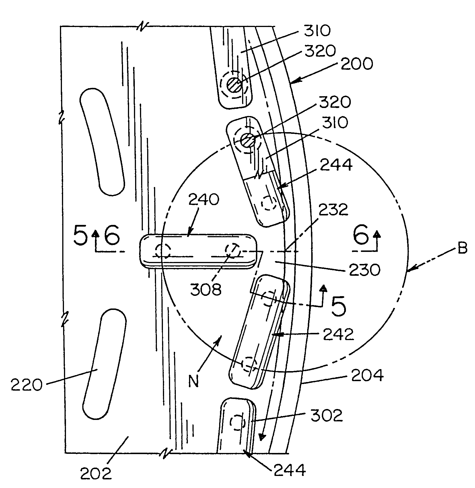
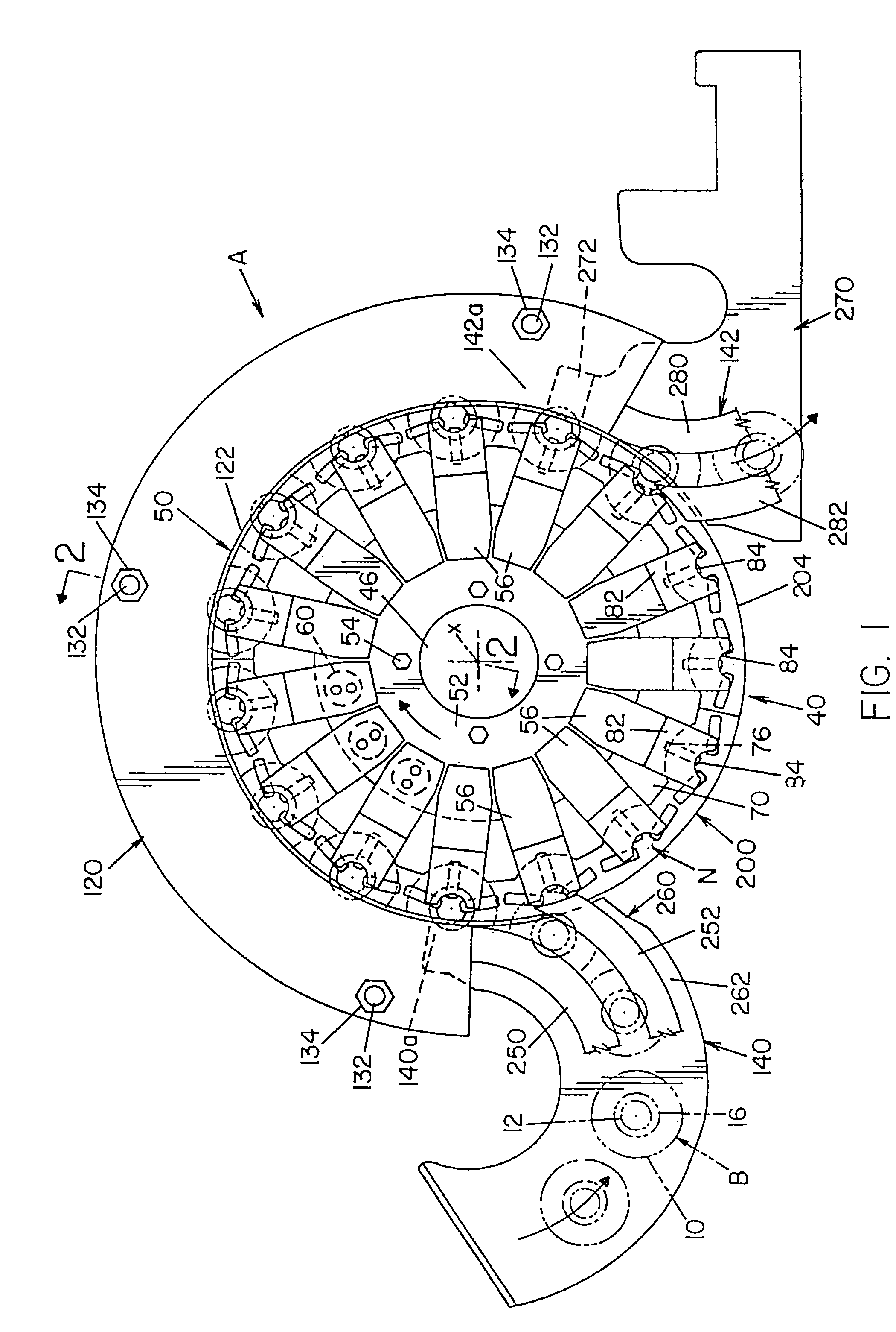
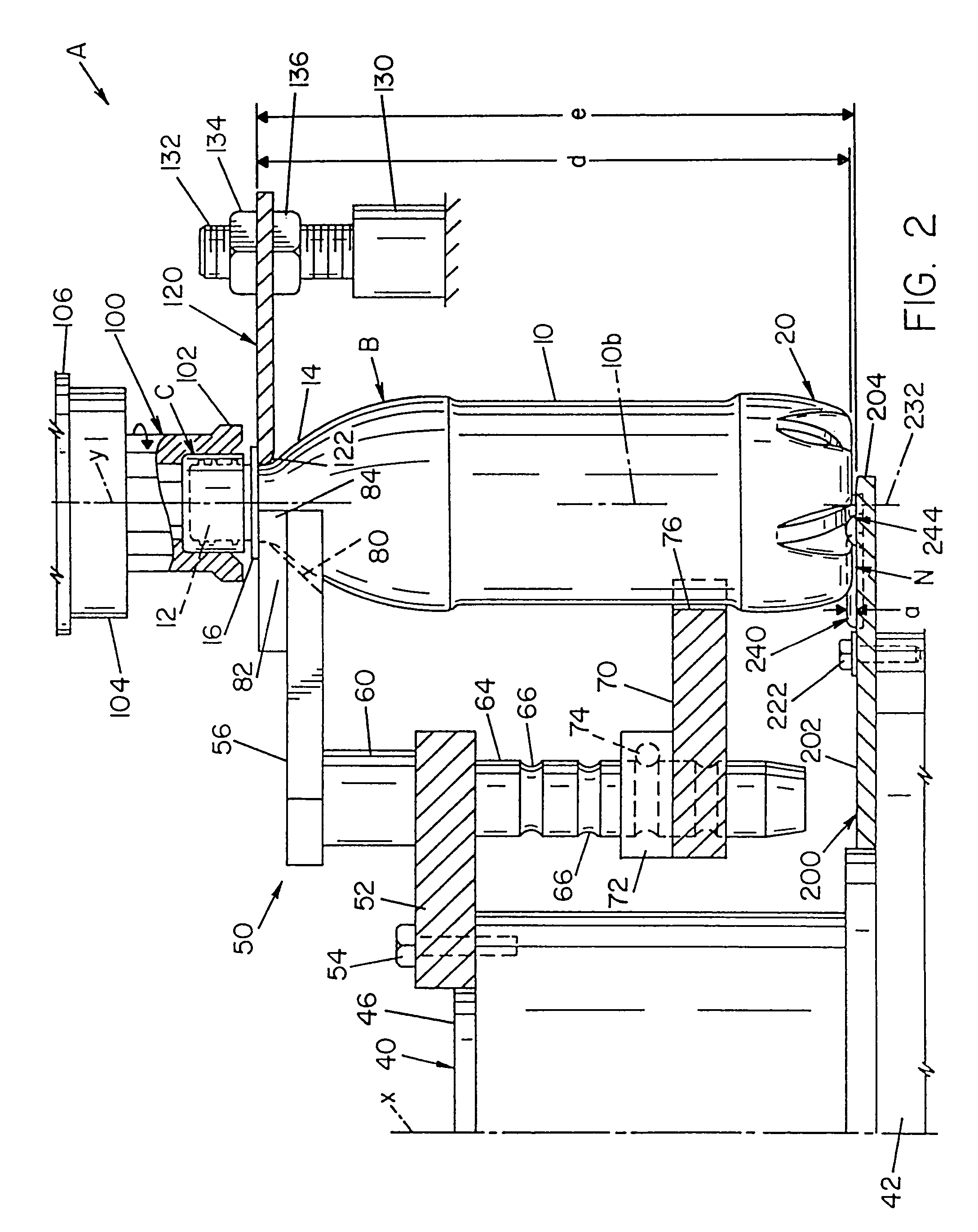
[0044]Referring now to the drawings wherein the showings are for the purpose of illustrating preferred embodiments of the invention only and not for the purpose of limiting same, FIGS. 1–3 illustrate a somewhat standard capping machine A of the type used in capping a plastic PET bottle B having various sizes and lengths. In accordance with the illustrated embodiment, bottle or container B includes a generally cylindrical body 10 having diameter 10a, center 10b and an upper threaded neck 12 connected to the body by diverging top portion 14 and provided with a circular flange 16. The base of container or bottle B is a pedaloid base 20, which is quite common in the plastic container industry for use with soft drinks and bottled beverages and is best shown in FIGS. 2, 6 and 7. A pedaloid base is a base with a number of distinct downwardly extending pads with flat surfaces divided by generally diverging recesses. In the illustrated embodiment, pedaloid base 20 includes five pads 20a–20e ...


PUM


Abstract

A bottle support structure and wear plate for use in a rotary capping machine used to apply caps onto the upper threaded neck of a series of plastic containers. The plastic containers have a generally cylindrical body with an outer cylindrical periphery with a diameter and a pedaloid base with spaced pads separated by radial recesses extending from a center recess. The bottle support structure supports the weight of the bottle as the bottle is being capped be prevent the body and base of the bottle from being deformed or crushed during the capping process. The wear plate is a flat ring rotated in unison with a star wheel about a machine axis. The ring has an upwardly facing flat surface and a series of container receiving nests movable in the circular path as the ring is rotated. Each of the nests has at least one elongated bar-like abutment projecting upwardly from the flat surface a given vertical distance. The one or more abutments prevent the bottle from rotating during the capping process.

Description

CONTINUING DATA[0001]The application is a continuation of U.S. application Ser. No. 10 / 330,463, filed Dec. 27, 2002, now abandoned, which is a continuation of U.S. application Ser. No. 09 / 537,373, filed Mar. 29, 2000, now abandoned.[0002]The present invention relates to the art of capping bottles or containers as they are moved along a preselected path and more particularly to a bottle support system and a wear plate in a capping machine which supports the bottle and prevents rotation of the while a cap is being tightened onto the neck of the bottle.[0003]The invention is particularly applicable to assembly of a cap onto a plastic bottle of the type having a pedaloid base constituting a plurality of protruding pads separated by diverging recesses or crevices. However the invention has much broader applications and can be used in applying a cap onto a bottle which has various protrusions on its base.INCORPORATION BY REFERENCE[0004]Peronek U.S. Pat. No. 4,939,890; Martin U.S. Pat. No....

Claims


Application Information

Patent Timeline
IPC IPC(8): B65B7/28B67B3/20
CPCB65B7/2835B67B3/2033B67B3/206
Inventor PERONEK, MICHAEL H.
Owner BEVCORP
Why Eureka
Eureka Blog
Learn More