Vinyl siding fastener

Inactive Publication Date: 2008-07-24
BLUEGRASS PRODS
View PDF32 Cites 20 Cited by
  • Summary
  • Abstract
  • Description
  • Claims
  • Application Information

AI Technical Summary

Benefits of technology

[0003]The present invention is premised on the realization that siding can be attached to a building with a fastener that includes a nail and a cup shaped washer. The cup shaped washer fits over the shank of the nail with the open end of the washer engulfing the head of the nail. The depth of the internal cavity of the washer is slightly greater than the thickness of the head of the nail. The washer is made from a rigid ma

Problems solved by technology

This interferes with expansion and contraction and can cause buckling of the siding.
As a result, a

Method used


Image

  • Vinyl siding fastener
  • Vinyl siding fastener
  • Vinyl siding fastener

Examples


Embodiment Construction

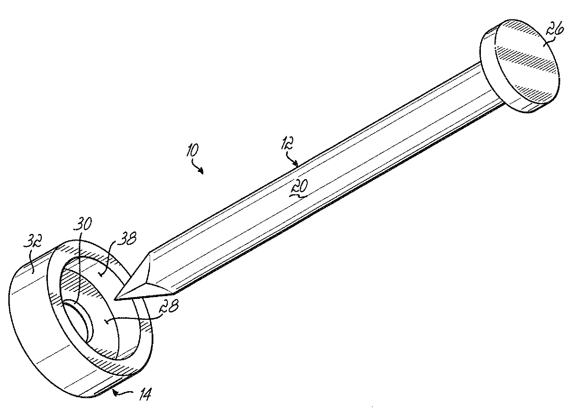
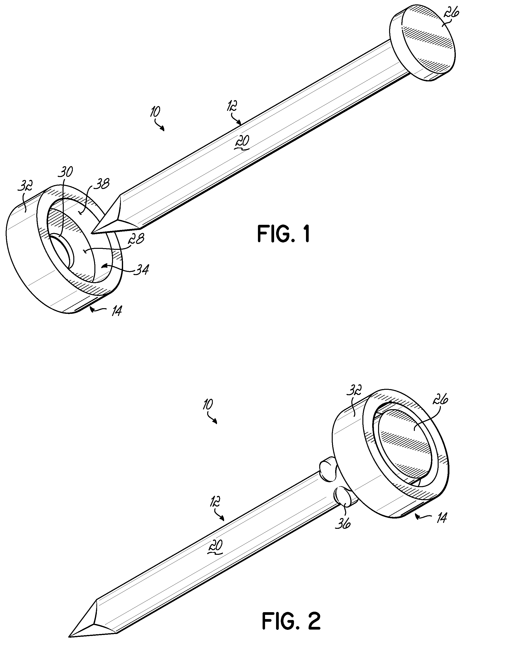
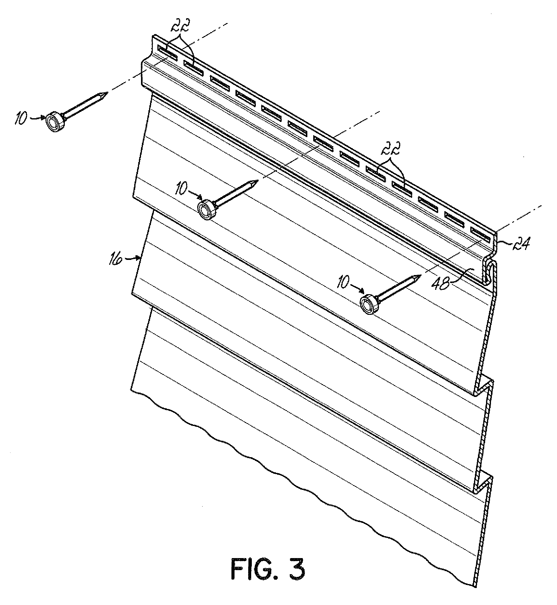
[0009]As shown in FIG. 1, a fastener 10 includes a nail 12 and a rigid cup shaped washer 14. This is used to attach siding 16 to the side wall 18 of a building by extending the shank 20 through a slot 22 in the nail flange 24 of the vinyl siding 16.

[0010]As shown in FIGS. 1 and 2, the nail 12 includes a shank 20 and a head 26.

[0011]The washer includes a bottom wall 28 having a central opening slightly larger than the shank 20 of the nail 12 and a side wall 32. The bottom wall 28 and side wall 32 combine to form an interior disc shaped cavity 34. The shank 20 of the nail 12 extends through the central opening 30 in the bottom wall 28 of the washer 14. Nail 12 can be held in place by a crimp 36 on the shank 20 of the nail 12.

[0012]As shown in FIG. 4, the inner side wall 38 of the cup shaped washer 14 has a depth that exceeds the thickness of the head 26 of the nail 12.

[0013]The fastener 10 is formed by combining the nail 12 with the washer 14. The diameter of the shank 20 of nail 12 s...


PUM


Abstract

A fastener for attaching siding to the wall of a building comprises a nail having a head and a shank and a cup shaped washer. The cup shaped washer has an internal cavity that is larger than the head of the nail so that when the nail is driven into the building through the nail flange of the siding, the head of the nail cannot be forced against the siding This provides clearance between the fastener and the siding allowing the siding to expand and contract as needed.

Description

BACKGROUND OF THE INVENTION[0001]Vinyl siding is generally attached to the side of a building using nails that extend through the nail flange of the vinyl siding. A nail flange includes a plurality of slots allowing the siding to be attached to the building along the entire length of the siding. The nails extend through the slots into the wall.[0002]Because vinyl siding expands and contracts significantly, the head of the nails must not press the siding tightly against the building wall. This interferes with expansion and contraction and can cause buckling of the siding. Therefore, when one nails siding to a wall, one should not drive the nail as far into the wall as possible. Rather, a slight gap should be left between the head of the nail and the nail flange. Unfortunately, this frequently does not occur. As a result, after the siding is applied, it buckles as the temperature changes creating an unsightly appearance.SUMMARY OF THE INVENTION[0003]The present invention is premised o...

Claims


Application Information

Patent Timeline
IPC IPC(8): F16B15/00F16B43/00
CPCF16B43/00F16B15/00
Inventor VAGEDES, MICHAEL
Owner BLUEGRASS PRODS
Why Eureka
Try Eureka