Replaceable blade offset snips

a technology of offset snips and blades, which is applied in the field of cutting tools, can solve the problems of unnecessarily short life span of conventional snips, reduced performance, and narrow levers, and achieve the effects of simultaneous replacement, fast and easy replacemen

Inactive Publication Date: 2008-08-07
MIDWEST TOOL & CUTLERY
View PDF13 Cites 13 Cited by
  • Summary
  • Abstract
  • Description
  • Claims
  • Application Information

AI Technical Summary

Benefits of technology

[0016]During operation, the offset and bent configuration of the snips allows material to pass through the blades and bypass the levers without interference and the configuration of the integral blade-bearing member with its bearing por...

Problems solved by technology

As with many types of snips, shears, and scissors, it is widely recognized that a substantial drawback associated with conventional snips is an unnecessarily short life span due to the cumulative wear on portions of the tool that engage the material being cut and that bear against and frictionally slide over each other during use.
Wear on the cutting edges of the blades results in dullness while wear on the opposing, inwardly-facing surfaces of the blades and thrust bearing surfaces surrounding the pivot causes a narrowing of the levers where those surfaces bear against each other.
Over time, the cumulative wear on the bearing surfaces leads to diminished performance and difficult operation of the snips.
Because the bearing surfaces of conventional snips cannot be replaced independently of the rest of the tool, replacement of the entire tool eventually becomes necessary.
Replacing the tool is costly and wasteful because those portions of the tool that do not experience significant wear must be discarded along with those that do.
While such snips provide a more economical way to maintain a tool with sharp cutting edges, they do not provide a solution that addresses a problem that arises because of wear on the thrust bearing surfaces of the tool that surround its pivot.
Unlike the cutting edges and inwa...

Method used


Image

  • Replaceable blade offset snips
  • Replaceable blade offset snips
  • Replaceable blade offset snips

Examples


Embodiment Construction

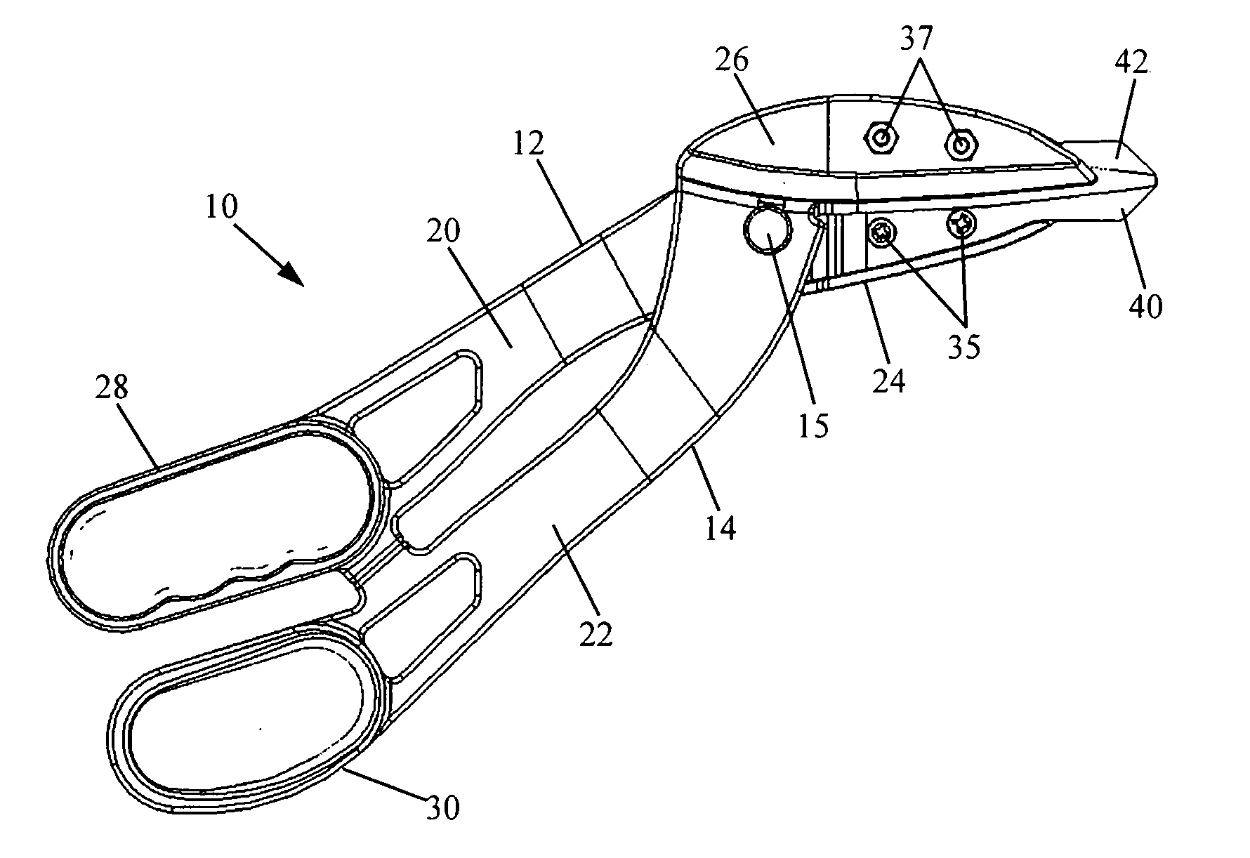
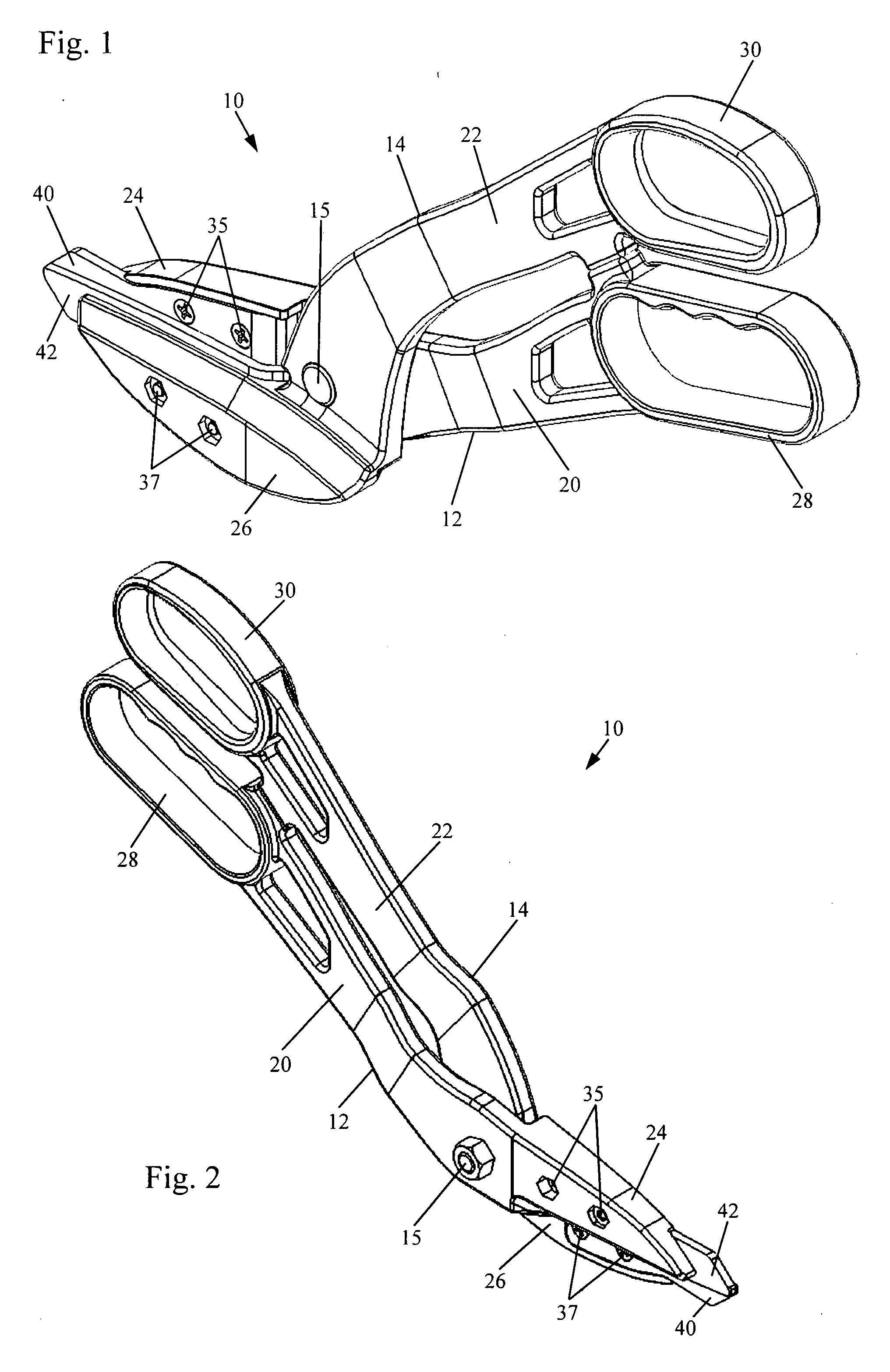
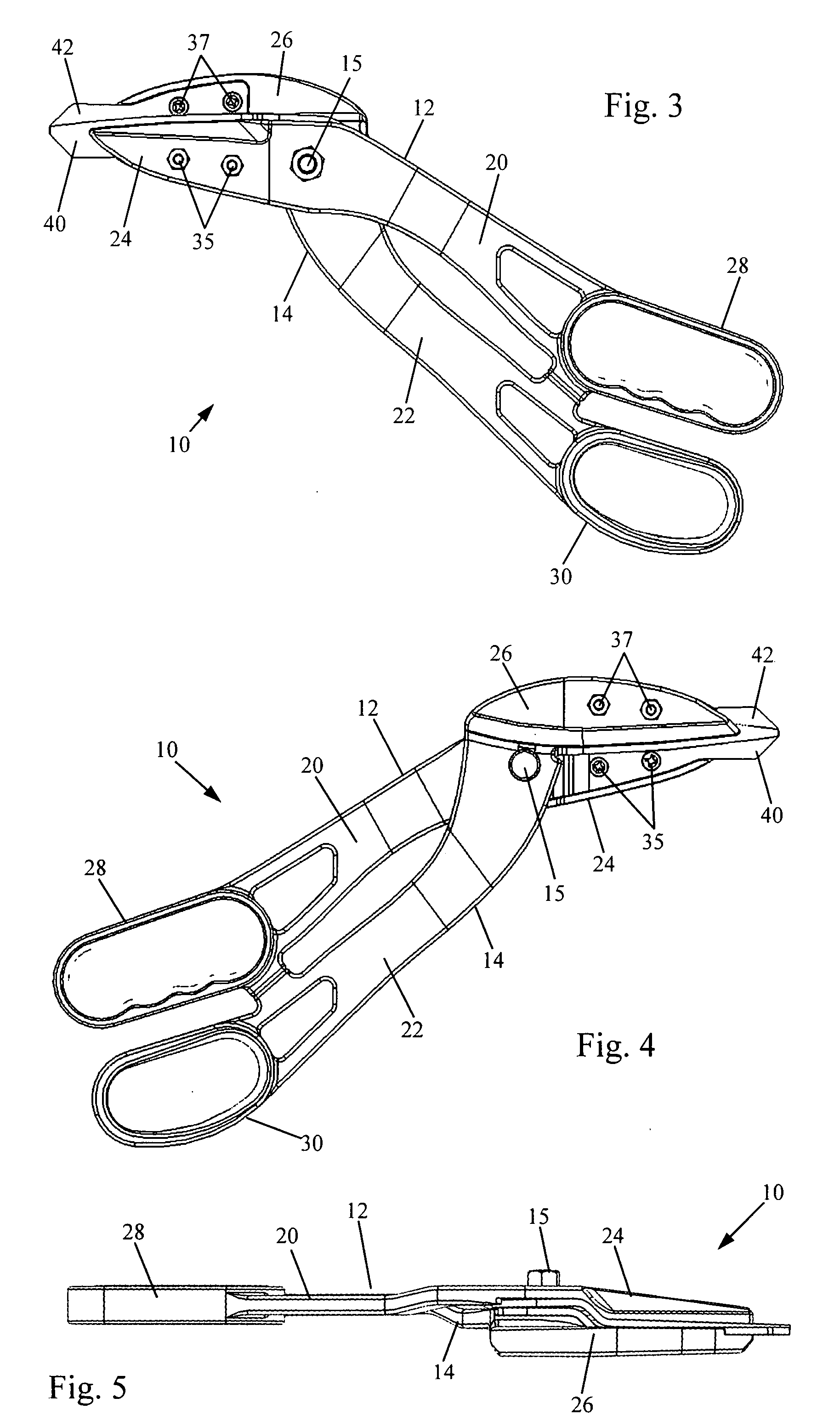
[0028]Referring to FIGS. 1-5, an illustrative embodiment of the snips in accordance with the present invention is indicated generally by the numeral 10. The snips embodying the invention are constructed of a pair of levers 12 and 14. The levers are pivotably connected to each other by a pivot fastener 15 that axially engages lever pivot apertures 16 and 18 (shown in FIGS. 6, 9, and 10) for allowing rotational movement of the levers 12 and 14 relative to one another. The pivot fastener 15 consists of a conventional nut-bolt combination, however all other means of rotatably interconnecting the levers 12 and 14 are also contemplated by this invention.

[0029]Referring again to FIGS. 1-5, each lever 12 and 14 consists of a hand grip lever arm 20 and 22 and a blade lever-arm 24 and 26 extending in substantially opposite directions from the pivot fastener 15. Each hand grip lever arm 20 and 22 and each blade lever-arm 24 and 26 has a proximal end that is closest to the pivot fastener 15 and...


PUM


Abstract

A handheld cutting snips having offset blades and bent levers, as well as replaceable blade and thrust bearing members. Bent levers and offset blades allow material being cut to pass through the cutting blades of the snips and bypass the levers without interfering with the levers or the hands of the snips' operator. Replaceable blade-bearing members allow simultaneous replacement of the snips' blades and surfaces surrounding the snips' pivot point, thereby preventing uneven wear and eventual blade interference and/or misalignment of the levers.

Description

(e) BACKGROUND OF THE INVENTION[0001]1. Field of the Invention[0002]The present invention relates generally to the field of cutting tools and more particularly to hand-operated snips and shears for cutting sheet metal or other stiff or rigid material.[0003]2. Description of the Related Art[0004]Metal cutting snips have been used in industry for many years. Conventional snips are typically constructed of two pivotally connected levers. Each lever has two lever arms extending in generally opposite directions from a pivot. One lever arm of each lever has a cutting blade at its end and the other lever arm of each lever has a hand grip at the opposite end. The hand grip lever arm is sometimes referred to as a handle.[0005]As with many types of snips, shears, and scissors, it is widely recognized that a substantial drawback associated with conventional snips is an unnecessarily short life span due to the cumulative wear on portions of the tool that engage the material being cut and that b...

Claims


Application Information

Patent Timeline
IPC IPC(8): B23D29/02
CPCB23D29/026B26B13/12B26B13/04
Inventor DETER, STEPHEN D.
Owner MIDWEST TOOL & CUTLERY
Why Eureka
Try Eureka