Header and chute attachment implements for header-chute assemblies of refrigeration systems

a technology of chute attachment and header-chute assembly, which is applied in the direction of domestic cooling apparatus, couplings, lighting and heating apparatus, etc., can solve the problems of difficult coordination or optimization of finalized sewing process, inability to easily exchange chute components within existing header-chute assemblies, and inefficiency or cost-effectiveness of the entire assembly process

Inactive Publication Date: 2008-08-14
PREMARK PACKAGING LLC
View PDF9 Cites 5 Cited by
  • Summary
  • Abstract
  • Description
  • Claims
  • Application Information

AI Technical Summary

Benefits of technology

[0007]The foregoing and other objectives are achieved in accordance with the teachings and principles of the present invention through the provision of new and improved header-chute assemblies having new and improved attachment implements for attachably and detachably securing together the header and chute components which are to be used within refrigeration systems incorporated within, for example, refrigeration truck or reefer trailers, wherein the attachment implements readily permit the repeated or interchangeable attachment and detachment of any particular header component to and from any particular chute component, or the attachment and detachment of any particular chute component to another chute component, without the need for specialized manufacturing assemblies. In this manner, multiple header and chute components may be maintained, for example, by the refrigeration truck or reefer trailer end-user or customer, and subsequently, depending upon, for example, the particular model of the refrigeration unit, or depending upon, for example, the particular configuration or design of the refrigerated air distribution chute, which is usually dependent upon, or a function of, the size of the refrigeration truck or reefer trailer, or depending upon the particular refrigeration parameters required for transporting particular refrigerated cargo loads, particularly desired header and chute components of the refrigeration system may be selected and readily assembled together on site or in the field by the refrigeration truck or reefer trailer user or customer personnel as opposed to necessarily being specially ordered from the header and chute manufacturer as a customized integral assembly. More particularly, the new and improved attachment implements may comprise, for example, zipper-type implements, hook and loop type implements, hinge type implements, or clamp type implements.

Problems solved by technology

Continuing further, in connection with providing the header and chute components to the end-user or customer, conventionally, the smaller, downstream or outlet end portion of the header component is permanently or fixedly attached to the upstream or inlet end portion of the chute component by means of a manufacturing process which comprises the sewing together of the header and chute components so as to in fact fabricate an integral header-chute assembly, however, this typical or conventional manufacturing process exhibits a multitude of deficiencies both from a manufacturing point of view as well as from an end-user or customer usage point of view.
In addition, the entire assembly process is not particularly efficient or cost-effective in view of the fact that the production rates, characteristic of the separate production lines separately manufacturing the header components and the chute components, differ from each other, thereby rendering the finalized sewing process difficult to coordinate or optimize.
In addition, different chute components cannot be readily exchanged within the existing header-chute assemblies because the header and chute components are fixedly assembled together, by means of the aforenoted sewing operation, as an integral entity.
Accordingly, the end-user or customer is forced to custom-order two different header-chute assemblies from the manufacturer whereby the end-user or customer will experience increased inventory costs.
In a similar manner, even if the end-user or customer is using the same reefer or refrigeration trailer, having the same reefer or refrigeration incorporated therein, to ship or transport two different cargo loads during two different or separate shipments, wherein the cargo loads may require or necessitate different refrigeration parameters, the end-user or customer may desire to use two different header-chute assemblies fabricated, for example, from different combinations of the aforenoted conventional materials, however, again, the different header or chute components cannot be readily exchanged within the existing header-chute assemblies because the header and chute components are fixedly assembled together, by means of the aforenoted sewing operation, as an integral entity.
Accordingly, the end-user or customer is again forced to custom-order two different header-chute assemblies from the manufacturer, thereby again experiencing increased inventory costs.
Still yet further, if either the header or chute component of the particular header-chute assembly should become worn, such as, for example, as a result of normal but continued usage over extended periods of time, or if the header or chute component of the particular header-chute assembly should become damaged, such as, for example, during various handling operations by means of motorized handling equipment, such as, for example, fork lift trucks or the like, the particularly damaged header or chute components of the header-chute assemblies cannot be readily interchanged or replaced.
Accordingly, the end-user or customer is again forced to custom-order an entirely new header-chute assembly from the manufacturer whereby, once again, the end-user or customer will experience increased product line costs.

Method used


Image

  • Header and chute attachment implements for header-chute assemblies of refrigeration systems
  • Header and chute attachment implements for header-chute assemblies of refrigeration systems
  • Header and chute attachment implements for header-chute assemblies of refrigeration systems

Examples


first embodiment

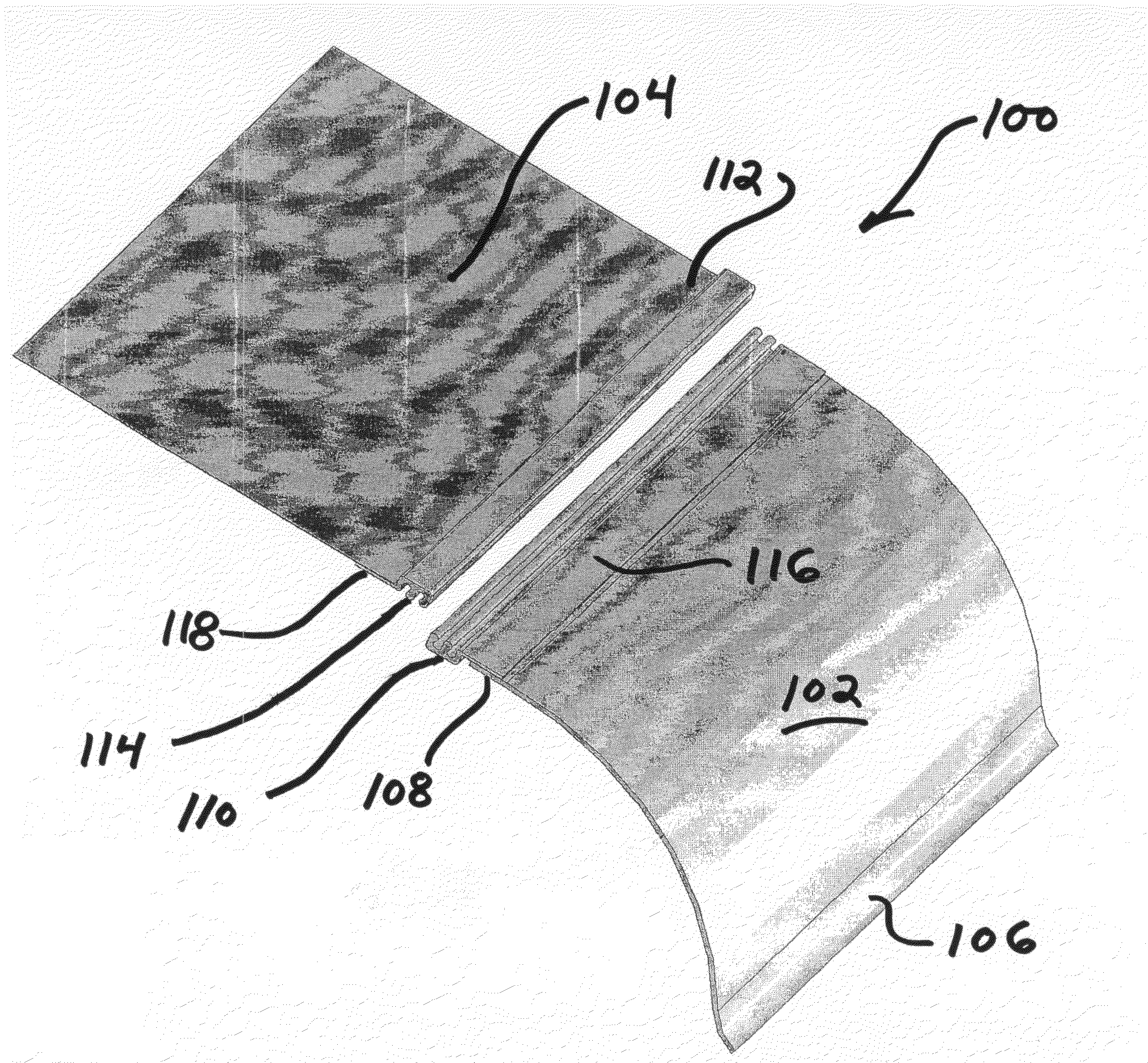
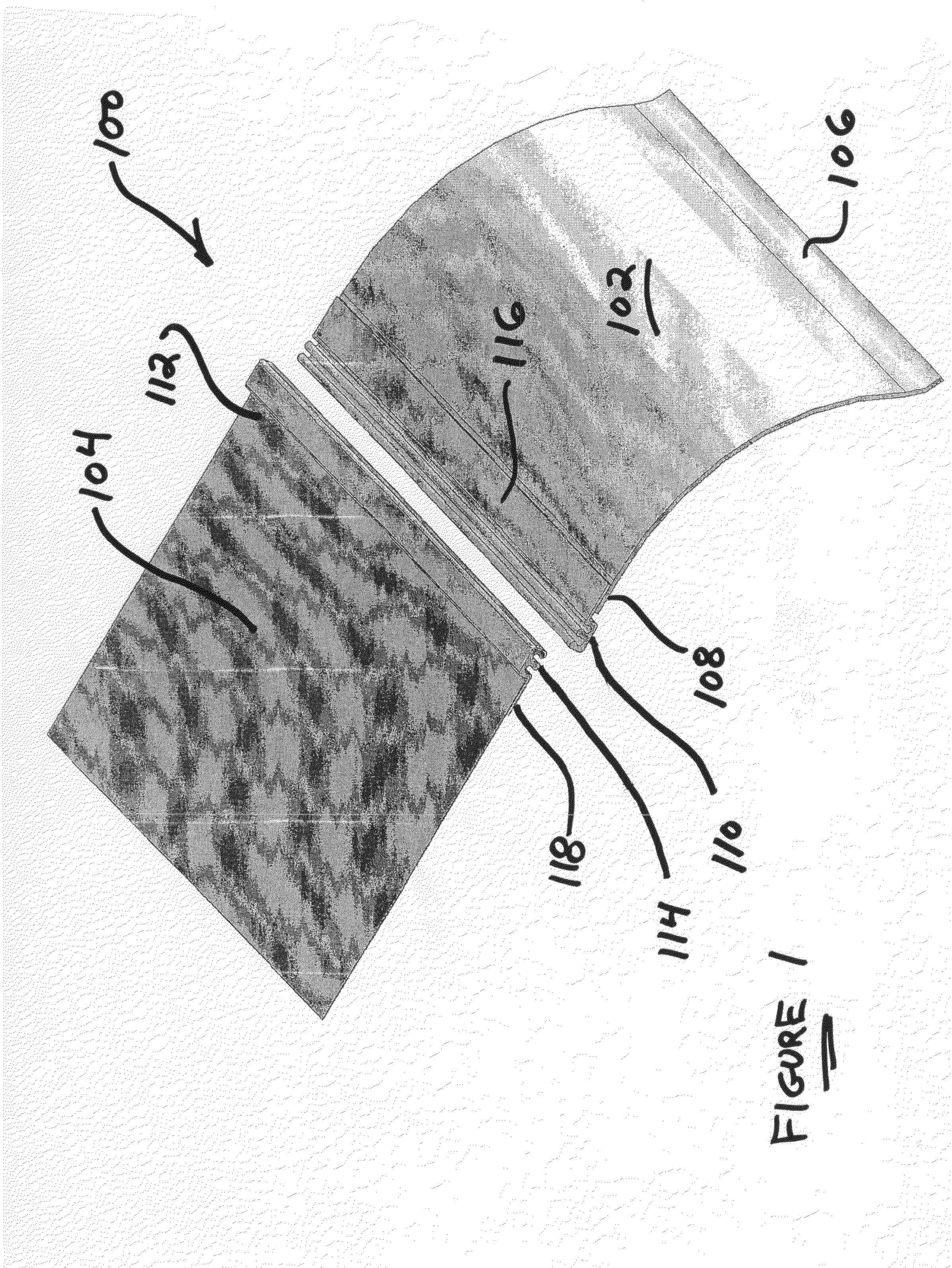
[0015]Referring now to the drawings, and more particularly to FIG. 1 thereof, a new and improved header-chute assembly, having new and improved attachment implements fixedly disposed upon the header and chute components of the new and improved header-chute assembly for attachably and detachably securing together the header and chute components which are to be used within refrigeration systems incorporated within, for example, refrigeration truck or reefer trailers, and constructed in accordance with the principles and teachings of the present invention, is disclosed and is generally indicated by the reference character 100. More particularly, part of a header component of the header-chute assembly 100 is disclosed at 102, while part of a chute component of the header-chute assembly 100 is disclosed at 104. An upstream or inlet end portion 106 of the header component 102 is adapted to be mated with and mounted upon a reefer or refrigeration unit, not shown, incorporated upon or withi...

fifth embodiment

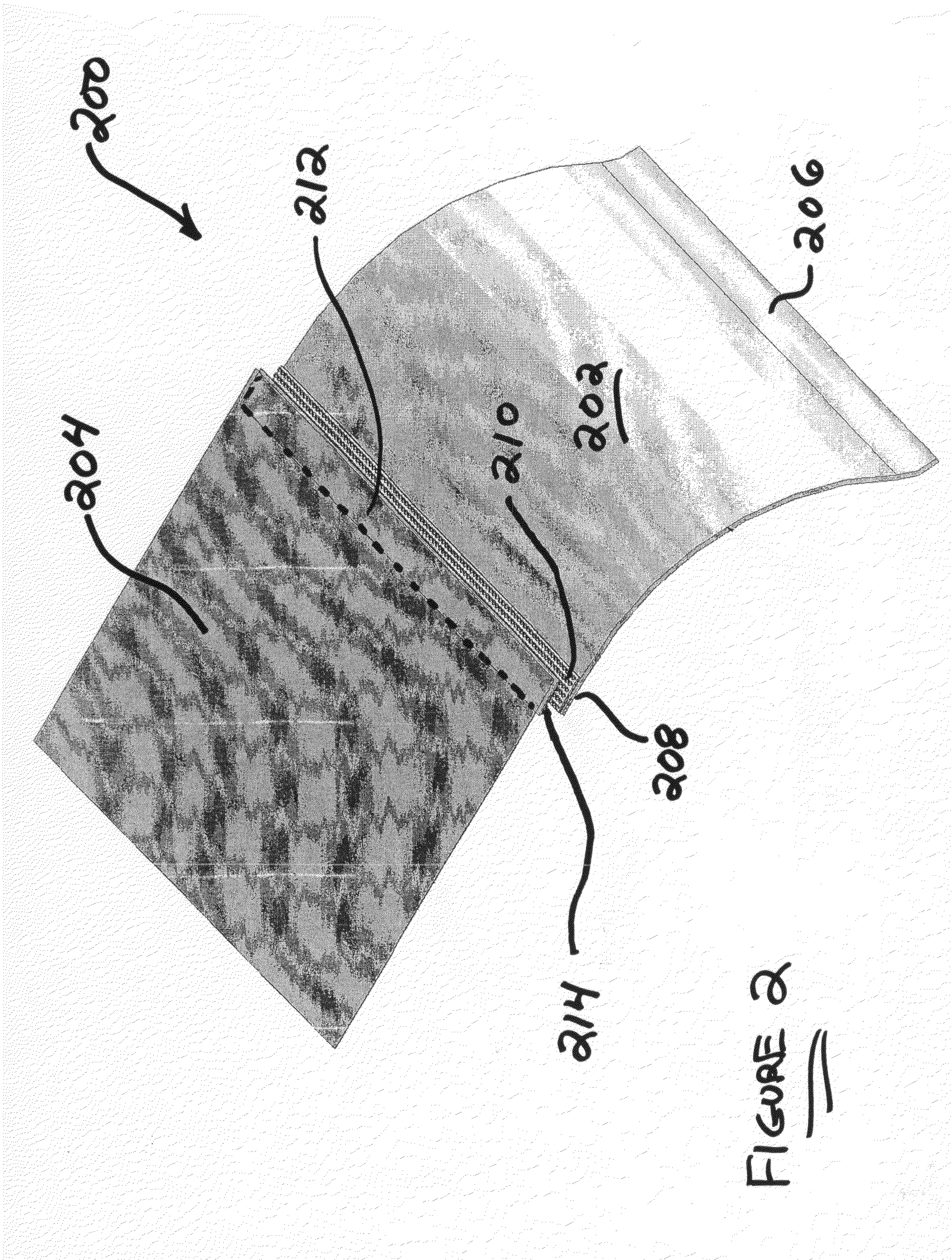
[0025]More particularly, it is seen that in accordance with the principles and teachings of the fifth embodiment header-chute assembly 500 of the present invention, the downstream or outlet end portion 508 of the header component 502 is folded downwardly or inwardly so as to be integrally formed into an attachment or connector implement having a substantially C-shaped cross-sectional configuration, while the upstream or inlet end portion 512 of the chute component 504 is integrally formed into a mating attachment or connector implement, having a substantially S-shaped cross-sectional configuration, wherein it can be seen that the lower arcuate section of the attachment or connector implement 512 effectively encases or covers the free end portion of the attachment or connector implement 508 while the upper arcuate section of the attachment connector or implement 512 is effectively disposed internally within the C-shaped attachment connector or implement 508. Still further, a clamping...


PUM


Abstract

Header and chute components of a refrigeration air distribution system have fastener attachment implements disposed thereon such that the header and chute components, or successive chute components, can be easily attached and detached with respect to each other by end-user customer personnel at on-site field locations. In addition, individual or particular header and chute components can be mixed and matched as may be desired, successive chute-components can be attached or detached with respect to each other in order to provide header-chute assemblies of varying length dimensions, and worn or damaged header and chute components may be readily replaced.

Description

FIELD OF THE INVENTION[0001]The present invention relates generally to refrigeration systems, and more particularly to new and improved attachment implements for securing together header and chute components which are used in connection with refrigeration systems incorporated within, for example, refrigeration truck or reefer trailers, wherein the attachment implements readily permit the repeated or interchangeable attachment and detachment of any particular header component to and from any particular chute component, or the attachment and detachment of any particular chute component to and from any other chute component, without the need for specialized manufacturing assemblies. In this manner, multiple header and chute components may be maintained, for example, by the refrigeration truck or reefer trailer user or customer, and subsequently, depending upon, for example, the particular model of the refrigeration unit, or depending upon, for example, the particular configuration or d...

Claims


Application Information

Patent Timeline
Patent Type & Authority Applications(United States)
IPC IPC(8): F25D19/00F16B5/12
CPCF25D17/045Y10T403/7043F25D23/006F25D19/003
Inventor CLARK, TOBYMCMAHON, MICHAEL J.PIOTROWSKI, STANLEY
Owner PREMARK PACKAGING LLC
Why Eureka
Try Eureka