
Vehicle safety system

a safety system and vehicle technology, applied in the field of vehicles, can solve the problems of limited driver's view and the problem of pillars, and achieve the effect of optimizing the view

Active Publication Date: 2008-08-21
VOXX INTERNATIONAL
View PDF8 Cites 13 Cited by
  • Summary
  • Abstract
  • Description
  • Claims
  • Application Information

AI Technical Summary

Benefits of technology

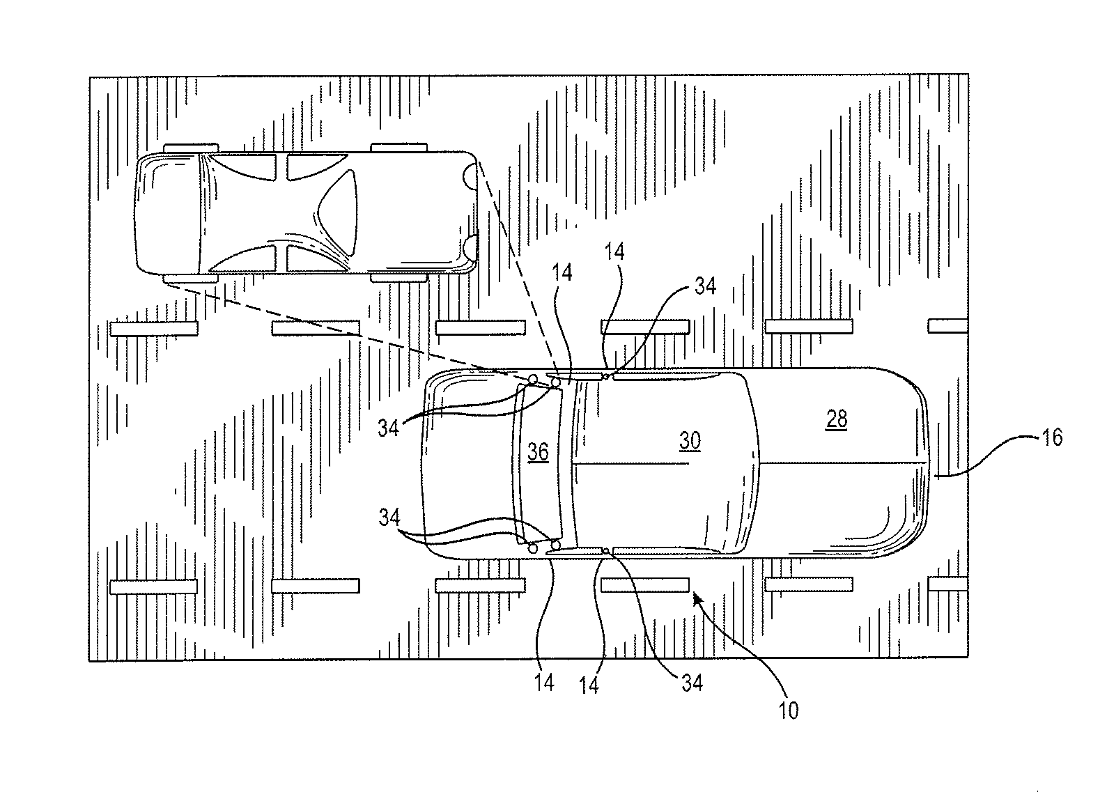
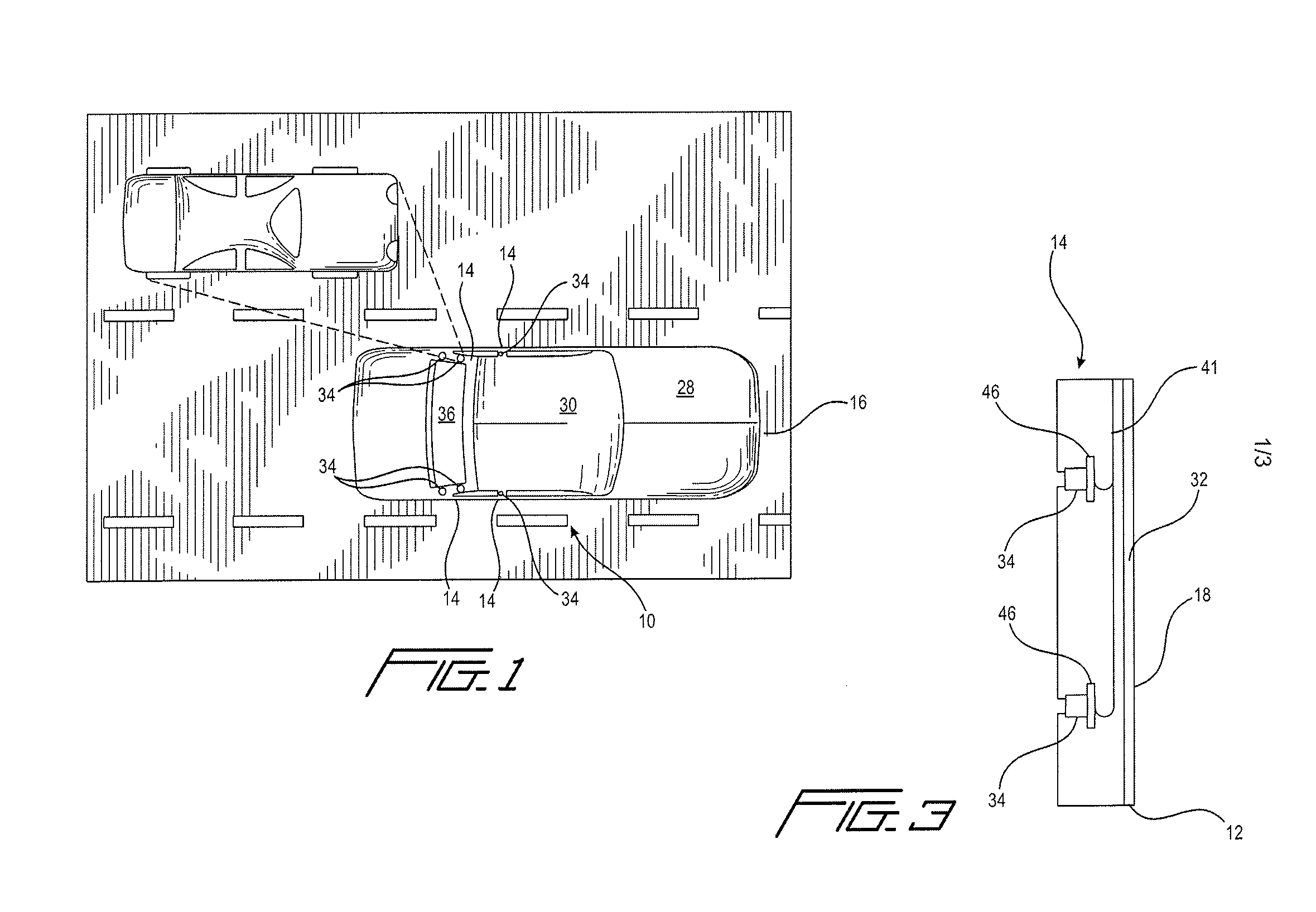
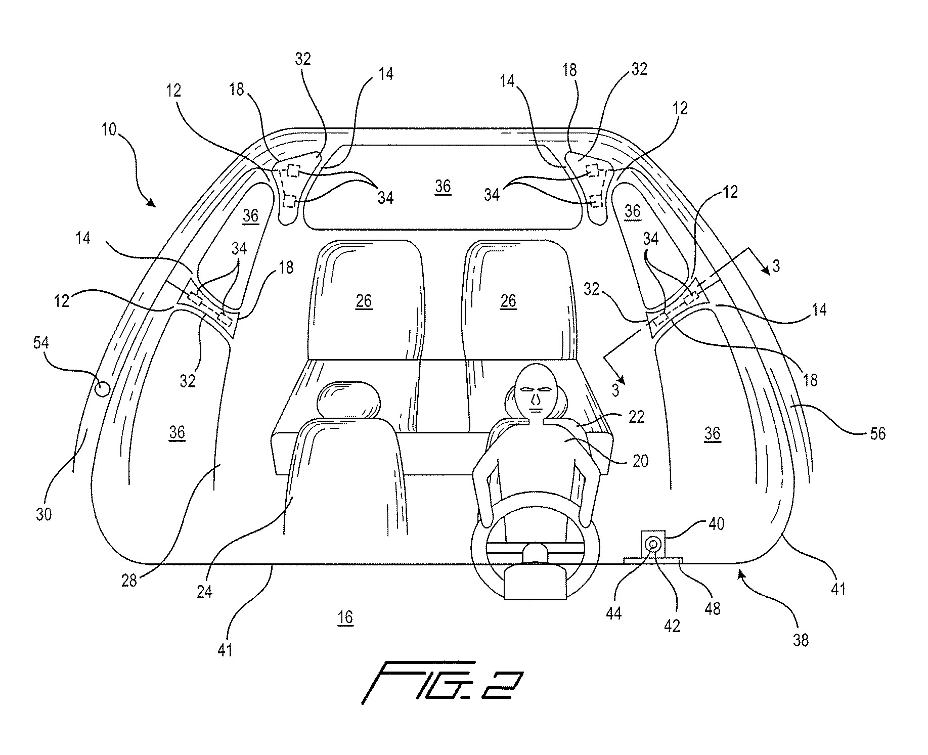
[0007]It is, therefore, an object of the present invention to provide a vehicle safety system including a vehicle having at least one pillar. The at least one pillar includes an inner surface covered with a display surface. An exterior focused camera is linked to the display surface for displaying an image taken by the camera upon the display surface, wherein the camera takes an image of the exterior area of the vehicle that a driver would otherwise see if the at least one pillar were not blocking the view of the driver. A camera control mechanism links a driver sitting within a driver seat of the vehicle to the camera such that the camera may be adjusted to optimize the view provided upon the display surface along the inner surface of the at least one pillar.

Problems solved by technology

These pillars always block a limited portion of the driver's view of the exterior environment, creating what are commonly referred to as “blind spots”.
While manufactures have attempted to provide more and more window area to minimize the effects of pillars in creating blind spots, the problems associated with pillars still remain.

Method used


Image

  • Vehicle safety system
  • Vehicle safety system
  • Vehicle safety system

Examples


Embodiment Construction

[0025]The detailed embodiments of the present invention are disclosed herein. It should be understood, however, that the disclosed embodiments are merely exemplary of the invention, which may be embodied in various forms. Therefore, the details disclosed herein are not to be interpreted as limiting, but merely as a basis for teaching one skilled in the art how to make and / or use the invention.

[0026]With reference to FIGS. 1 to 3, an automobile safety system 10 is disclosed. In accordance with a preferred embodiment of the present invention, the inner surfaces 12 of the pillars 14 located within an automobile 16 are covered with respective display surfaces 18 such that objects which would otherwise be blocked by the pillars 14 are shown on the display surfaces 18. As a result, a driver 20 looking rearwardly or sidewardly within his or her automobile 16 can see objects which would otherwise be blocked by the pillars 14. Although the present invention is disclosed with reference to aut...


PUM


Abstract

A vehicle safety system includes a vehicle having at least one pillar. The at least one pillar includes an inner surface covered with a display surface. An exterior focused camera linked to the display surface for displaying an image taken by the camera upon the display material, wherein the camera takes an image of the exterior area of the vehicle that a driver would otherwise see if the at least one pillar were not blocking the view of the driver. A camera control mechanism links a driver sitting within a driver seat of the vehicle to the camera such that the camera may be adjusted to optimize the view provided upon the display surface along the inner surface of the at least one pillar.

Description

CROSS REFERENCE TO RELATED APPLICATION[0001]This application claims the benefit of U.S. Provisional Patent Application Ser. No. 60 / 902,345, filed Feb. 21, 2007, and entitled “AUTOMOBILE SAFETY SYSTEM”.BACKGROUND OF THE INVENTION[0002]1. Field of the Invention[0003]The present invention relates to vehicle safety systems. More particularly, the invention relates to a display system along the interior surface of the pillars of an automobile allowing a driver, or a passenger, to see objects that would otherwise be obstructed by the pillars of an automobile.[0004]2. Description of the Prior Art[0005]All automobiles include pillars that connect the primary body of the automobile to the roof of the automobile. These pillars always block a limited portion of the driver's view of the exterior environment, creating what are commonly referred to as “blind spots”. The size of these blind spots is directly related to the width of the pillars used in an automobile. While manufactures have attempt...

Claims


Application Information

Patent Timeline
Patent Type & Authority Applications(United States)
IPC IPC(8): B60Q1/00
CPCB60Q1/50B60R1/00B60R2011/0022B60R2300/202H04N7/181B60R2300/60B60R2300/802B60R2300/8093B60R2300/301B60R1/28B60R1/25
Inventor VITITO, CHRISTOPHER J.
Owner VOXX INTERNATIONAL
Learn More