
External storing device, image processing apparatus and image forming apparatus respectively comprising the external storing device

Inactive Publication Date: 2008-08-21
OKI DATA CORP
View PDF3 Cites 1 Cited by
  • Summary
  • Abstract
  • Description
  • Claims
  • Application Information

AI Technical Summary

Benefits of technology

[0017]According to the present invention, it is possible to make the other unallowed image forming apparatus be unable to use the option data or the option program even if having read out them from the allowed image forming apparatus having

Problems solved by technology

However, in the image forming system comprising the external apparatus and the above-stated plural conventional image forming apparatuses, with respect to one image forming apparatus in which the option data / option program and the efficient program are provided, there is a problem that other image forming apparatus which is not allowed to use reads out the option program and the efficient program and executes them, or, reads the option data and the efficient program and uses them.

Method used


Image

  • External storing device, image processing apparatus and image forming apparatus respectively comprising the external storing device
  • External storing device, image processing apparatus and image forming apparatus respectively comprising the external storing device
  • External storing device, image processing apparatus and image forming apparatus respectively comprising the external storing device

Examples


embodiment 1

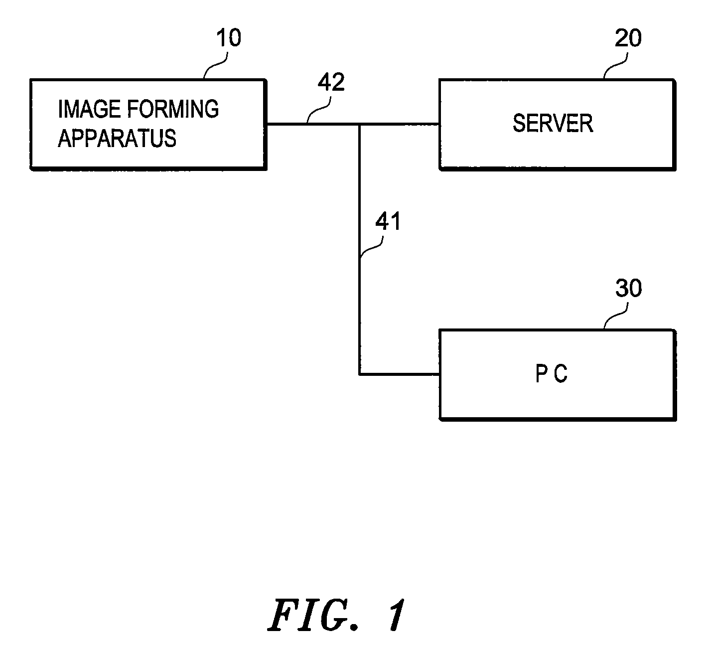
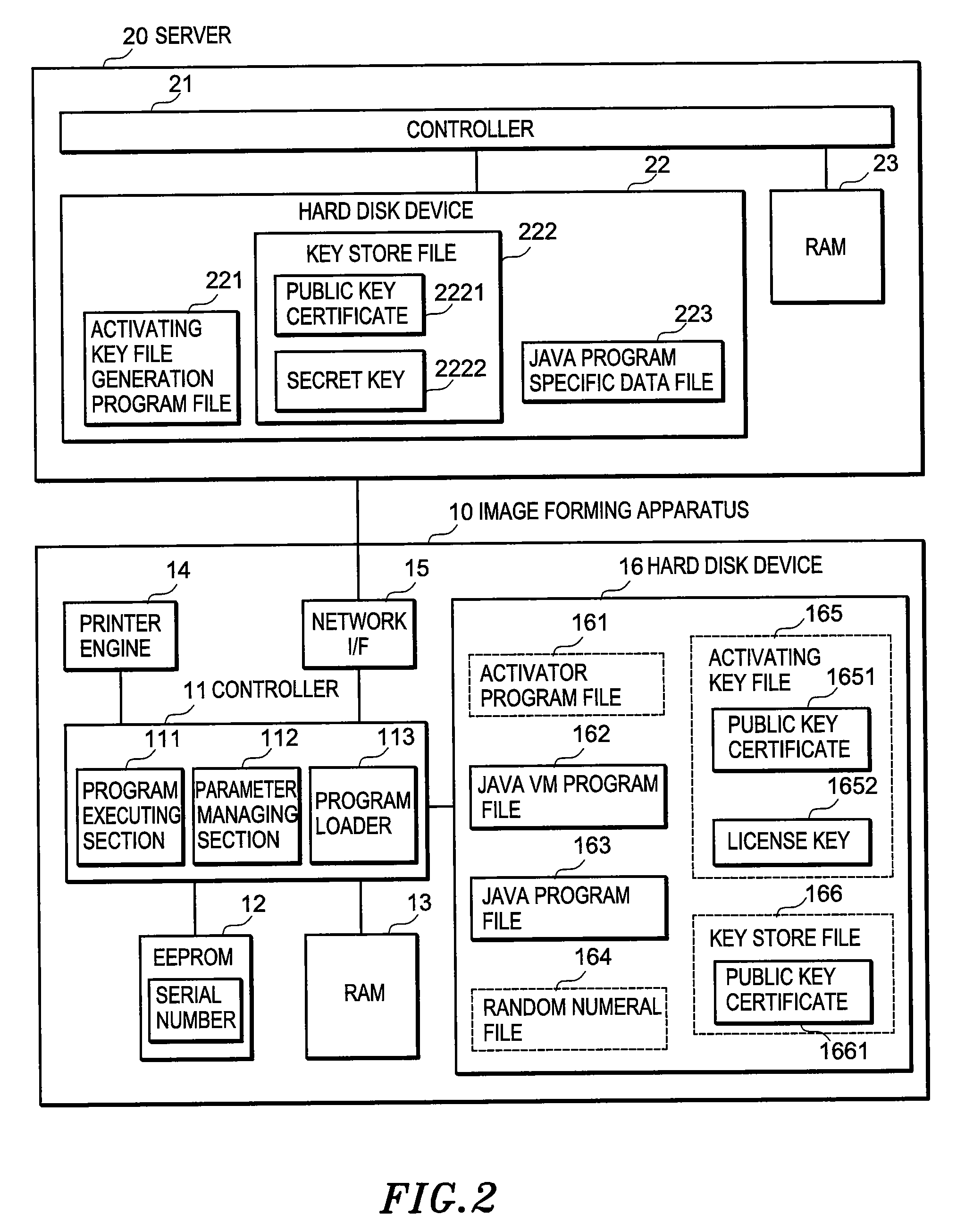
[0031]FIG. 1 is a block diagram showing a use state of an image forming apparatus in embodiment 1 of the present invention; and FIG. 2 is a block diagram showing a structure of an image forming apparatus in embodiment 1 of the present invention.

[0032]As shown by FIG. 1, an image forming apparatus 10 in embodiment 1, for example, as a printer, is connected with a server 20 via cable 41, also is connected with a PC 30 via cable 42. As shown by FIG. 2, the image forming apparatus 10 comprises a controller 11, an EEPROM 12, a RAM 13, a printer engine 14, a network I / F 15 and a hard disk device 16.

[0033]The controller 11 forms a program executing section 111, a parameter managing section 112, and a program loader 113 that are stated below through executing main control program stored in a ROM (not shown).

[0034]The program executing section 111 executes activator program stored in an activator program file 161 existing in the hard disk device 16; Java (Trademark) VM (Virtual Machine) prog...

embodiment 2

[0117]FIG. 7 is a block diagram showing a use state of an image forming apparatus in embodiment 2 of the present invention; and FIG. 8 is a block diagram showing a structure of an image forming apparatus in embodiment 2 of the present invention.

[0118]As shown by FIG. 7, an image forming apparatus 50 in embodiment 2 is connected with a PC 30 via cable 41. As shown by FIG. 8, the image forming apparatus 50 comprises a controller 51, an EEPROM 52, a RAM 53, a printer engine 54, a network I / F 55 and a hard disk device 56.

[0119]The controller 51 forms a program executing section 511, a parameter managing section 512, and a program loader 513 that are stated below through executing main control program stored in a ROM (not shown).

[0120]The program executing section 511 of the controller 51 has the same function as the program executing section 111 in embodiment 1, further has other function. That is, after registration key is stored in the RAM 53, the program executing section 511 outputs...


PUM


Abstract

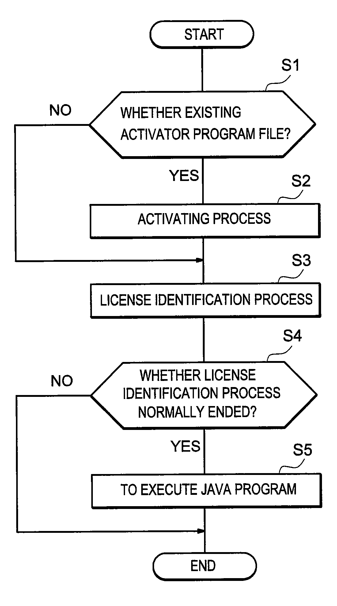
The present invention has an object to make the unallowed image forming apparatus be unable to use option data or option program even if having read out them from the allowed image forming apparatus having the option data or the option program. In an image forming apparatus, a program executing section judges whether the image forming apparatus meets identification information described in a license key stated in activating data in activating key file when executing Java program serving as option program, and executes the Java program in the case that the image forming apparatus meets the identification information.

Description

BACKGROUND OF THE INVENTION[0001]1. Field of the Invention[0002]The invention relates to an external storing device that receives a supply of option program or option data from an external apparatus and stores the option program or option data; image processing apparatus and image forming apparatus respectively comprises the external storing device.[0003]2. Related Background Art[0004]In conventional image forming apparatus, in general, according to different price, different function is provided. Therefore, in the case that such conventional image forming apparatus adds new function, after option data or option program for executing the new function and efficient program for activating (in a use allowance state) the option data or the option program are provided from a server or an external apparatus such as PC and the like, it is necessary to use the provided efficient program to activate the provided option data or the provided option program (e.g. refer to patent document 1). Th...

Claims


Application Information

Patent Timeline
IPC IPC(8): G06F3/12G06F21/00G06F21/10G06F21/12G06F21/33G06F21/60G06F21/62G06F21/64
CPCG06F21/608
Inventor TAKAMUNE, TOSHIAKI
Owner OKI DATA CORP
Learn More