RFID Gate Antenna

a technology of rfid gate and antenna, which is applied in the direction of antenna details, antennas, basic electric elements, etc., can solve the problems of difficult to use conventional rfid gate in small shops or self-service shops in limited space, and the rfid gate doesn't work well

Inactive Publication Date: 2019-05-16
LAI CHUNG PING
View PDF5 Cites 0 Cited by
  • Summary
  • Abstract
  • Description
  • Claims
  • Application Information

AI Technical Summary

Benefits of technology

[0013]The present RFID gate antenna features on that both detecting angle and directivity of the RFID gate antenna are modified for being applied to entrance and exit of small shops or stores. Thus the problem of the conventional RFID gate antenna that it is unable to be used in small shops or stores is solved.

Problems solved by technology

There are some technical problems involved in the use of RFID gate (such as UHF RFID gate) in intelligent convenience stores or self-service stores now.
The UHF RFID reader antenna available now in the RFID gate easily scans all tags within the range including tags on people or shelves nearby so that the RFID gate doesn't work well.
Thereby the conventional RFID gate is difficult to be used in limited space of small shops or self-service shops.

Method used


Image

  • RFID Gate Antenna
  • RFID Gate Antenna
  • RFID Gate Antenna

Examples


Embodiment Construction

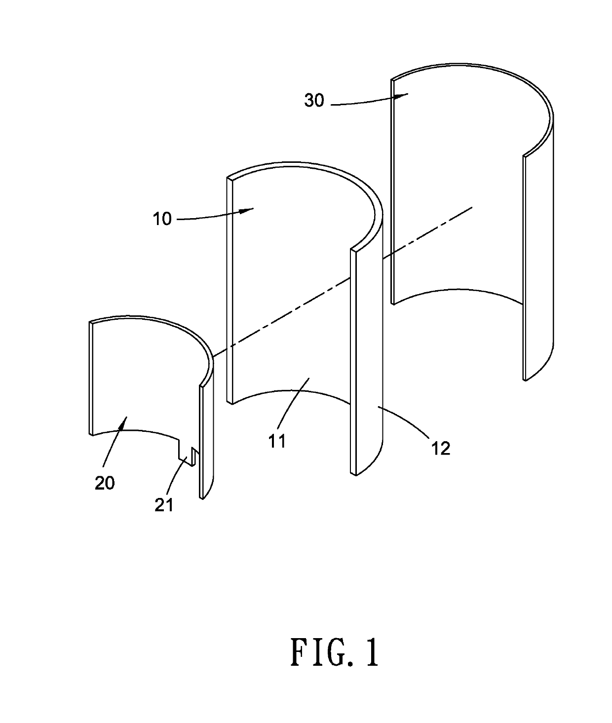
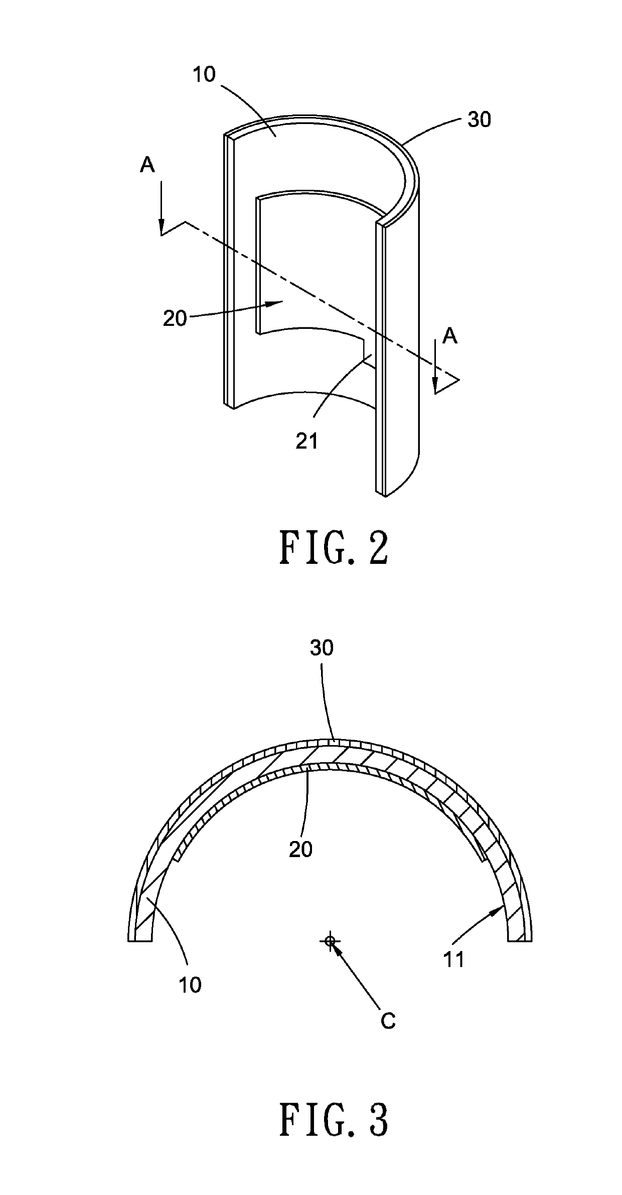
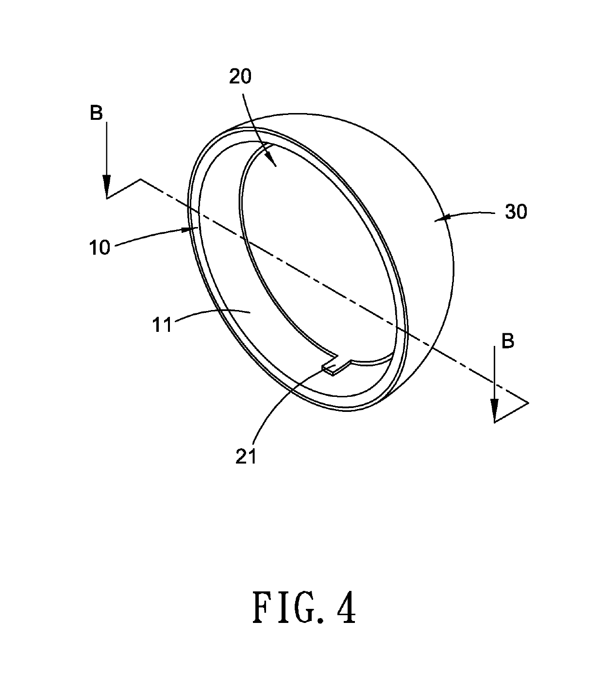
[0022]Refer to FIG. 1, FIG. 2 and FIG. 3, a RFID gate antenna according to the present invention includes a dielectric layer 10, a patch layer 20 and a ground layer 30. The present RFID gate antenna is a patch antenna used as a radio transmitter and receiver of a RFID gate.

[0023]The dielectric layer 10 is a sheet-like part made from dielectric material and having a surface. An inner surface 11 is disposed on one side of the dielectric layer 10 and an outer surface 12 is arranged at the other side of the dielectric layer 10, opposite to the inner surface 11. The inner surface 11 is a surface located on one side of the dielectric layer 10 and facing the center of curvature C of the surface of the dielectric layer 10. The patch layer 20 disposed with a feed point 21 is attached to the inner surface 11 of the dielectric layer 10 and is used as a radiator for radiating power (generally called patch antenna). In this embodiment, the patch layer 20 shown in FIG. 1 is, but not limited to, a...


PUM


Abstract

A radio-frequency identification (RFID) gate antenna is revealed. The RFID gate antenna includes a dielectric layer, a patch layer and a ground layer. The dielectric layer is a sheet-like part made from dielectric material and having an inner surface and an opposite outer surface. The inner surface is a surface located on one side of the dielectric layer and facing the center of curvature. The patch layer including a feed point is attached to the inner surface of the dielectric layer. The ground layer is attached to the outer surface of the dielectric layer, opposite to the patch layer. The RFID gate antenna features on modification of detecting angle and directivity thereof for being applied to entrance and exit of small shops or stores. Thereby the shortcoming of the conventional RFID gate antenna that it is unable to be used in small shops or stores is overcome.

Description

BACKGROUND OF THE INVENTIONField of the Invention[0001]The present invention relates to a radio frequency identification (RFID) gate, especially to a RFID gate antenna.Description of Related Art[0002]Nowadays goods on open shelves in shopping malls are generally disposed with Electronic Article Surveillance Systems (EAS Systems) for monitoring and preventing shoplifting. The EAS system is mainly composed of detectors, a deactivator and electronic tags. There are several major types of EAS systems including magnetic systems, radio frequency systems (RF System), electromagnetic systems and microwave systems. The RF systems and the magnetic systems are commonly used. The RF system benefits the user in terms of low installation cost. Electronic tags disposed with receiving antennas and used for storage of digital information (such as product information) are attached to the goods respectively. RFID tags are one of the most common electronic tags for preventing shoplifting and inventory ...

Claims


Application Information

Patent Timeline
Patent Type & Authority Applications(United States)
IPC IPC(8): H01Q1/22H01Q9/04H01Q1/38
CPCH01Q1/2216H01Q9/0407H01Q1/38
Inventor LAI, CHUNG-PING
Owner LAI CHUNG PING
Why Eureka
Try Eureka