
Apparatus and method for administering reduced pressure treatment to a tissue site

a tissue site and reduced pressure technology, applied in the field of tissue treatment, can solve the problems of limiting the mobility of both the treatment system and the person to whom the treatment is being applied, the complexity of the current reduced pressure treatment system precludes a person with little or no specialized knowledge from administering such treatment to oneself or others, and the inability to achieve the effect of reducing the risk of infection

Active Publication Date: 2008-08-21
KCI LICENSING INC
View PDF103 Cites 184 Cited by
  • Summary
  • Abstract
  • Description
  • Claims
  • Application Information

AI Technical Summary

Problems solved by technology

Currently, the use of reduced pressure treatment is not considered a viable or affordable option for low-severity wounds due to the manpower required to monitor and change system components, the requirement for trained medical personnel overseeing treatment, and the high cost of treatment.
For example, the complexity of current reduced pressure treatment systems precludes a person with little or no specialized knowledge from administering such treatment to oneself or others.
The size and power consumption characteristics of current reduced pressure treatment systems also limit the mobility of both the treatment system and the person to whom the treatment is being applied.
Also, the high cost of current reduced pressure treatment systems can preclude the accessibility of such treatment systems to some users.
Current reduced pressure treatment systems are also typically non-disposable after each treatment.
However, the inclusion of the added component of a fluid container increases the obtrusiveness, complexity, and weight of the reduced pressure treatment system, thereby increasing the discomfort and limiting the mobility of the patient.
Current reduced pressure treatment systems also lack user-friendly, non-obtrusive methods for indicating whether an adequate amount of reduced pressure is being applied to the tissue site by the reduced pressure treatment system.
Therefore, persons with specialized knowledge are required in order to properly operate the reduced pressure treatment system, thereby increasing the cost and decreasing the accessibility of using the reduced pressure treatment system.

Method used


Image

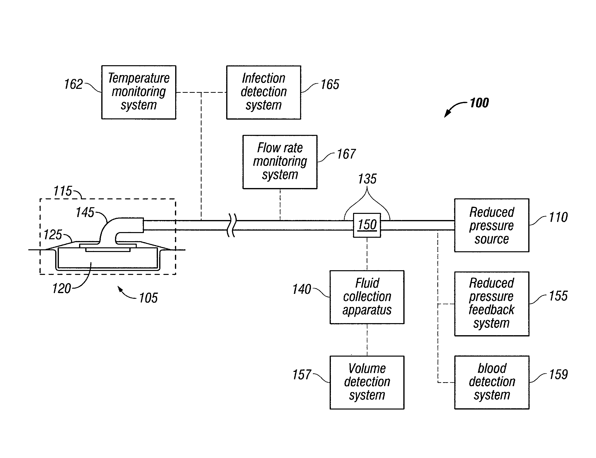
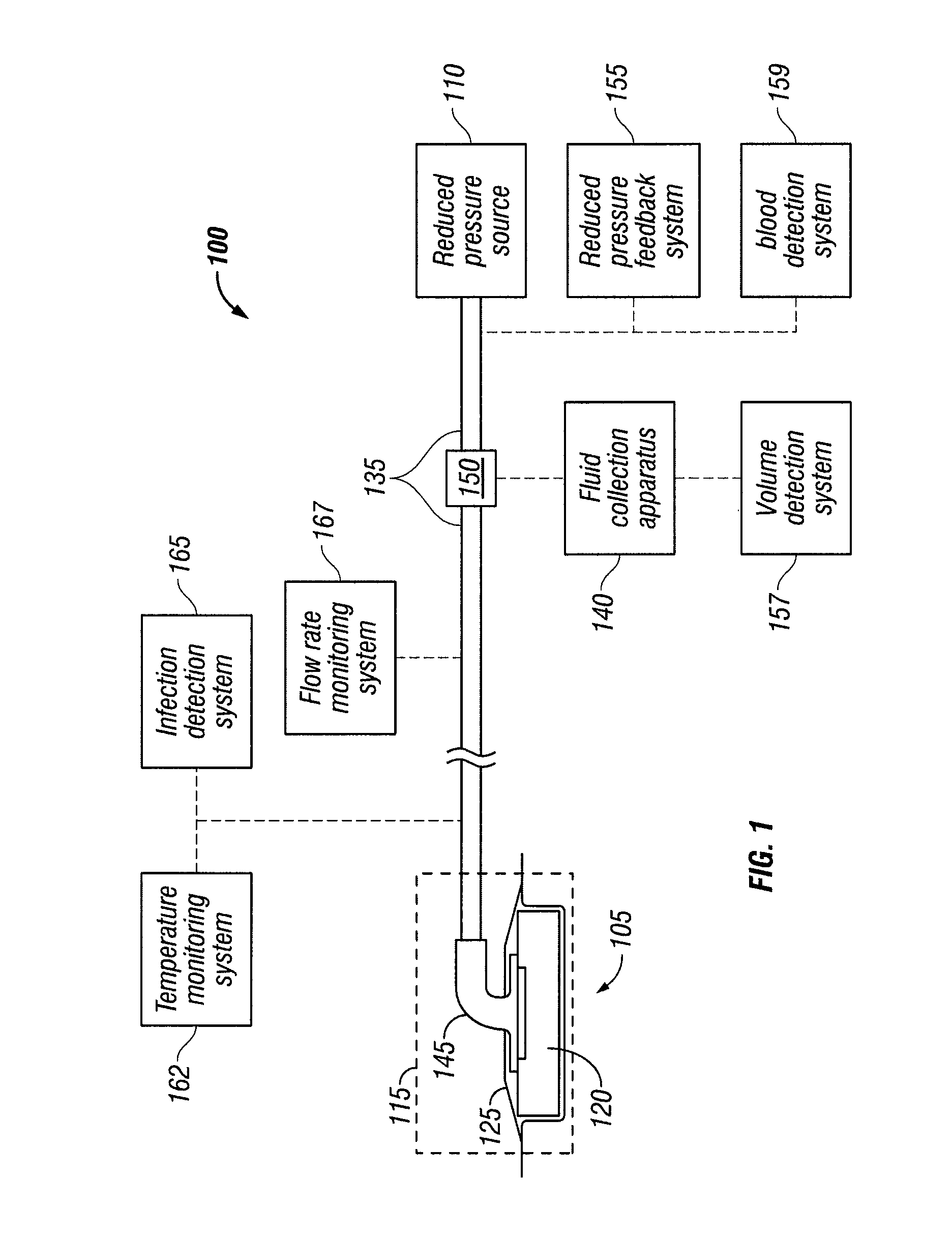
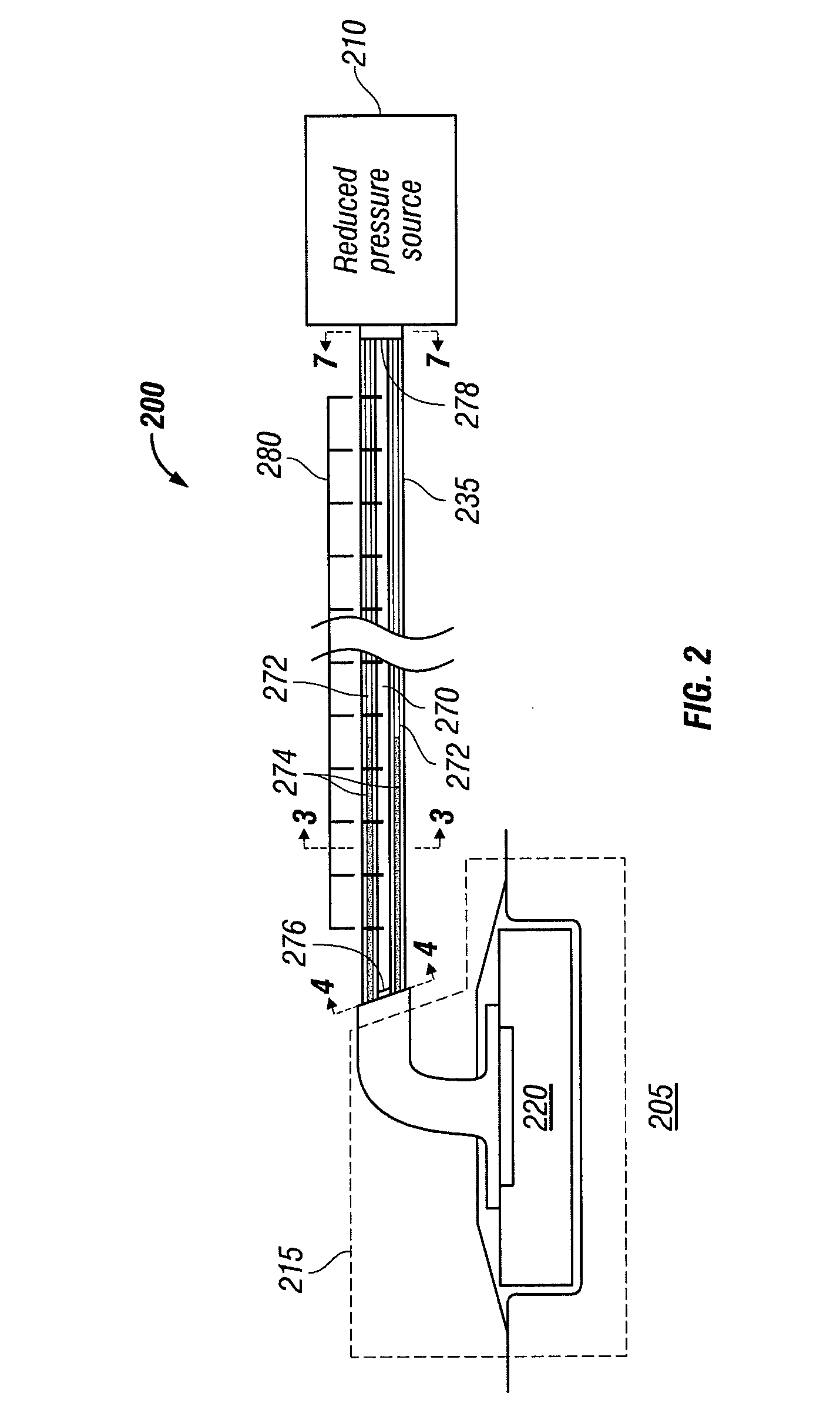
  • Apparatus and method for administering reduced pressure treatment to a tissue site
  • Apparatus and method for administering reduced pressure treatment to a tissue site
  • Apparatus and method for administering reduced pressure treatment to a tissue site

Examples


Embodiment Construction

[0029]In the following detailed description of the preferred embodiments, reference is made to the accompanying drawings that form a part hereof, and in which is shown by way of illustration specific preferred embodiments in which the invention may be practiced. These embodiments are described in sufficient detail to enable those skilled in the art to practice the invention, and it is understood that other embodiments may be utilized and that logical structural, mechanical, electrical, and chemical changes may be made without departing from the spirit or scope of the invention. To avoid detail not necessary to enable those skilled in the art to practice the invention, the description may omit certain information known to those skilled in the art. The following detailed description is, therefore, not to be taken in a limiting sense, and the scope of the present invention is defined only by the appended claims.

[0030]The illustrative embodiments described herein provide an apparatus an...


PUM


Abstract

The illustrative embodiments described herein are directed to a system and method for administering reduced pressure at a tissue site. The apparatus includes a reduced pressure source. The reduced pressure source generates a reduced pressure. The apparatus includes a tube having a plurality of lumens. The plurality of lumens includes at least one collection lumen. The reduced pressure source applies the reduced pressure to the tissue site through the plurality of lumens such that the at least one collection lumen receives fluid from the tissue site. The at least one collection lumen stores the fluid received from the tissue site.

Description

CROSS-REFERENCE TO RELATED APPLICATIONS[0001]This application claims the benefit of U.S. Provisional Application No. 60 / 900,415, filed Feb. 9, 2007. Priority is claimed to the above-mentioned application, and this application is hereby incorporated by reference.BACKGROUND OF THE INVENTION[0002]1. Field of the Invention[0003]The present invention relates generally to the field of tissue treatment, and more specifically to a system and method for applying reduced pressure at a tissue site.[0004]2. Description of Related Art[0005]Clinical studies and practice have shown that providing a reduced pressure in proximity to a tissue site augments and accelerates the growth of new tissue at the tissue site. The applications of this phenomenon are numerous, but application of reduced pressure has been particularly successful in treating wounds. The treatment of wounds using reduced pressure is sometimes referred to in the medical community as “negative pressure tissue treatment,”“reduced pres...

Claims


Application Information

Patent Timeline
IPC IPC(8): A61M27/00
CPCA61M1/0001A61M1/0049A61M1/0088A61M25/0029A61M27/00A61M1/0027A61M2025/004A61M2205/3344A61M2205/3379A61M2205/7536A61M2205/15A61M2025/0036A61M1/732A61M1/78A61M1/882A61M1/915A61M1/92A61M1/60A61M1/916A61M1/982A61M1/00A61M37/00A61M1/73A61M2205/3334A61M2205/583A61M2205/7527
Inventor SANDERS, T. BLANEHEATON, KEITH PATRICKHARDMAN, LAN JAMESLOCKE, CHRISTOPHER BRIANROBINSON, TIMOTHY MARKBEARD, MARK STEPHEN JAMESJAEB, JONATHAN PAULKIESWETTER, KRISTINEJOHNSON, ROYCE W.INGRAM, SHANNON C.
Owner KCI LICENSING INC
Learn More