
Method and System for Concurrent Message Processing

a message processing and concurrent technology, applied in the field of concurrent message processing, can solve the problems of considerable overhead and limited message fields on which the intermediary can perform

Inactive Publication Date: 2008-08-21
IBM CORP
View PDF6 Cites 19 Cited by
  • Summary
  • Abstract
  • Description
  • Claims
  • Application Information

AI Technical Summary

Benefits of technology

The present invention provides a mechanism for processing multiple messages simultaneously at an intermediary while releasing them in the original order. This allows for the performance of logic at the intermediary without restricting its functions. The method includes retrieving messages from an input queue, starting a transaction for processing each message, and operating the transactions to ensure the messages are released in the original order. The system includes an input queue, intermediary, output queue, and transaction management means to ensure the messages are released in the correct order. The computer program product includes computer code means for performing the steps of the invention.

Problems solved by technology

In another example, the fields in the message on which the intermediary can perform may be limited.
However, this obvious solution results in considerable overheads.

Method used


Image

  • Method and System for Concurrent Message Processing
  • Method and System for Concurrent Message Processing
  • Method and System for Concurrent Message Processing

Examples


first embodiment

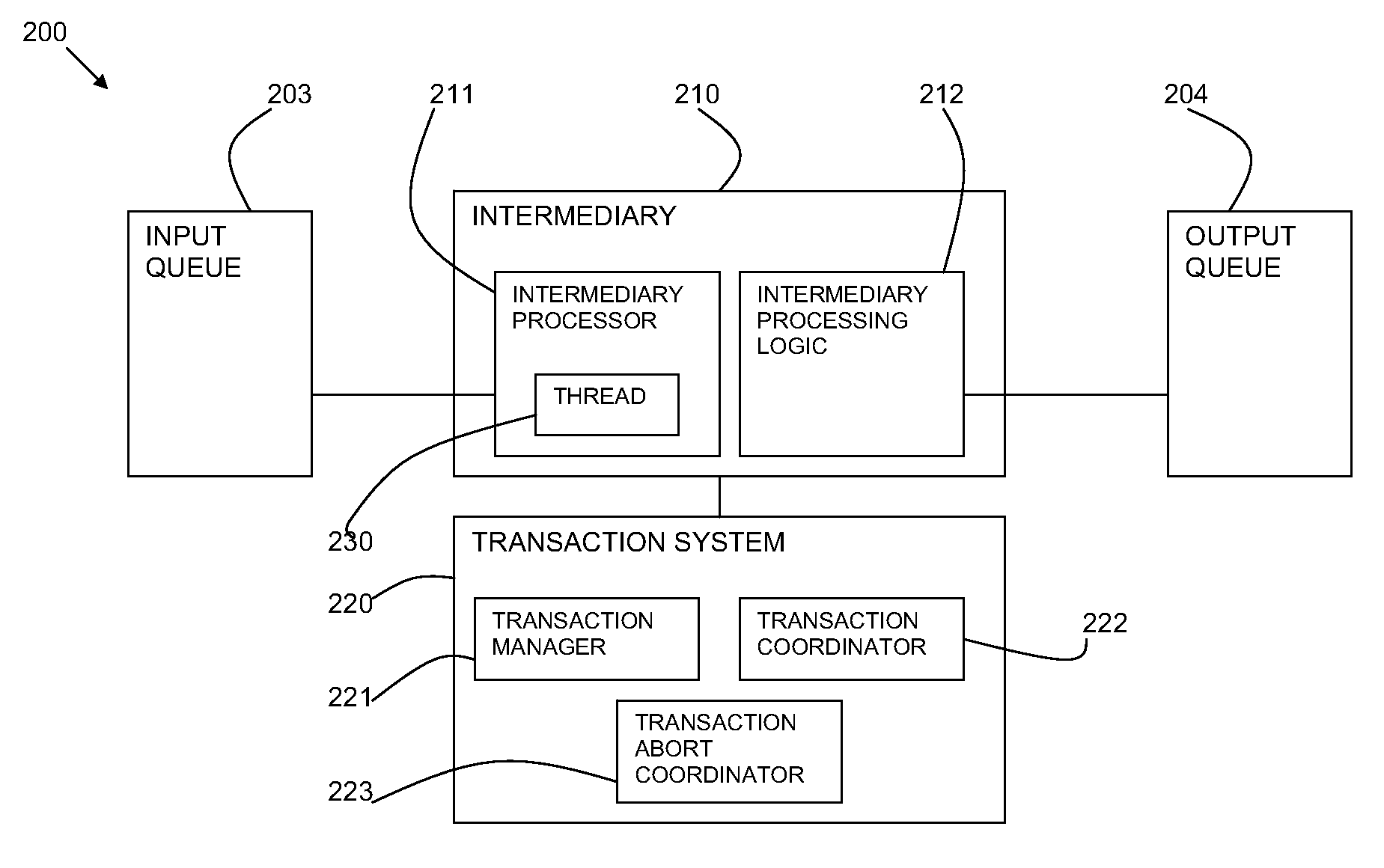
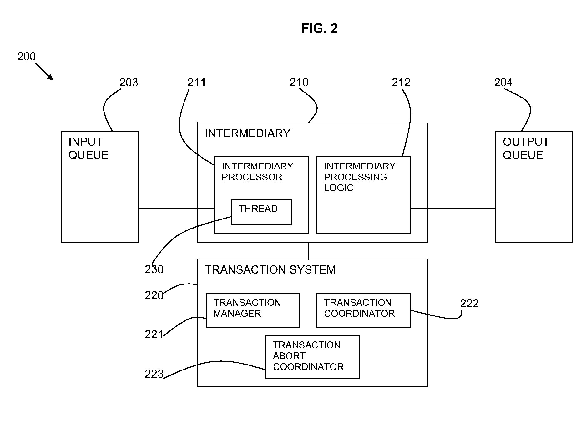
[0063]FIG. 3 is a representation of the method steps of the first embodiment between the components of the input queue 203, the intermediary processor 211, the transaction coordinator 222, the transaction manager 221, the intermediary processing logic 212, and the output queue 204.

[0064]A message is available 301 to the intermediary processor 211 from the input queue 203. The intermediary processor 211 registers 302, 303 the message order with the transaction coordinator 222. The intermediary processor 211 then allocates 304 the message to a thread 230. The thread 230 creates a transaction 305 at the transaction coordinator 222 and the transaction coordinator 222 begins the transaction 306, 307 at the transaction manager 221 and confirmation is returned 308 to the thread 230.

[0065]The thread 230 gets the message 309 under the transaction and the message is sent 310 to the thread 230. The message is then processed 311 by the intermediary processing logic 212 and put 312 under the tra...

second embodiment

[0068]In the second embodiment, the transaction management system 220 provides create-time ordering, in which output messages are released to the output queue in the order in which the transactions were created. In this embodiment, there is no transaction coordinator 222.

[0069]Under the approach of the second embodiment, the step of the method of the first embodiment of informing the transaction management system of where the message is in the order is replaced by the step of calling the transaction management system to start a new transaction. The message and the new transaction are then both passed to a new thread for parallel processing, and subsequent committing of the transaction.

[0070]FIG. 4 is a representation of the method steps of the second embodiment between the components of the input queue 203, the intermediary processor 211, the transaction manager 221, the intermediary processing logic 212, and the output queue 204.

[0071]A message is available 401 to the intermediary ...


PUM


Abstract

A method and system are provided for concurrent message processing. The system includes: an input queue capable of receiving multiple messages in a given order; an intermediary for processing the messages; and an output queue for releasing the messages from the intermediary. Means are provided for retrieving a message from an input queue for processing at the intermediary and starting a transaction under which the message is to be processed. The intermediate logic processes the transactions in parallel and a transaction management means ensures that the messages are released to the output queue in the order of the messages in the input queue.

Description

BACKGROUND[0001]1. Field of the Invention[0002]This invention relates to the field of concurrent message processing. In particular, it relates to concurrent message processing of asynchronous messages at an intermediary.[0003]2. Description of the Related Art[0004]A common requirement of asynchronous message queuing systems is for the order of messages sent to any queue to be maintained. This means that a first message sent before a second message must be received by the consumer in that order.[0005]The enforcement of message ordering has many implications for the processing of messages. One of these relates to the processing of messages by an intermediary.[0006]Intermediaries may process messages in various different ways by performing logic between the senders and the receivers of messages. An example intermediary is a message broker that translates a message from the formal messaging protocol of the sender to the formal messaging protocol of the receiver in a telecommunication ne...

Claims


Application Information

Patent Timeline
Patent Type & Authority Applications(United States)
IPC IPC(8): G06F9/46
CPCG06F9/546G06F9/466
Inventor NOTTINGHAM, ALASDAIRROBERTS, MATTHEWVINES, DAVID JOHN
Owner IBM CORP
Learn More