Steering Apparatus

a technology of steering apparatus and composing members, which is applied in the direction of steering parts, steering columns, vehicle components, etc., can solve the problems of increasing the size of the tilt type electric steering column apparatus, raising another problem, increasing the number of parts, etc., and reducing the size of the apparatus. , the rigidity of the composing members of the steering column oscillation shift mechanism can be enhanced, and the generation of a strange noise offensive to the ear can be prevented sufficiently

Inactive Publication Date: 2008-09-11
NSK LTD
View PDF0 Cites 32 Cited by
  • Summary
  • Abstract
  • Description
  • Claims
  • Application Information

AI Technical Summary

Benefits of technology

[0117]According to the above-structured tilt type electric steering apparatus of the invention, the number of parts and the size of the apparatus can be reduced, the rigidity of the composing members of a steering column oscillation shift mechanism can be enhanced sufficiently, and the generation of a strange noise offensive to the ear can be prevented sufficiently.
[0118]That is, according to the invention, one of the first and second elements, which cooperate together in constituting the moving member of the electric actuator, can be rotated about a rotation center axis parallel to the tilt pivot shaft with respect to the steering column or vehicle body side bracket, and the first and second elements can be shifted with respect to each other in a direction perpendicular both to the rotation center axis of the connecting element portion and to the longitudinal direction of the screw shaft or fixed member. Therefore, without using two or more link mechanisms, the linear movement caused by the electric actuator can be converted to the arc-shaped movement (oscillation) of the steering column, thereby being able to reduce the number of parts and size of the present electric steering apparatus. Also, it is possible to enhance sufficiently the rigidity of the composing members constituting the oscillation shift mechanism which is used to oscillate and shift the steering column. Further, it is possible to allow the oscillation shift mechanism to fulfill its normal function stably and also to prevent an unreasonable force from being applied to the oscillation shift mechanism
[0119]Also, according to the invention, the two end portions of the screw shaft or fixed member can be supported not through two or more separate members which are oscillated and shifted with respect to each other. Owing to this, regardless of the oscillation shift of the stee...

Problems solved by technology

However, in the above-mentioned conventional structure disclosed in the patent reference 1, there are found the following problems to be solved.
Accordingly, in the above-mentioned conventional structure, there is found a problem that the number of parts increases, the rigidity of the expansion rod 12 functioning as a composing part to constitute an oscillation shift mechanism for oscillate the steering column 4 is lowered, and the size of the tilt type electric steering column apparatus tends to increase.
However, in this structure, there is raised another problem.
Therefore, an unreasonable force is applied to the oscillation shift mechanism of the steering column and, in a bad case, the oscillation shift mechanism is unable to function properly.
However, this makes it difficult to enhance the working precision of the male screw portion and, as a result of this, the nut member tends to shift with respect to the screw shaft while oscillating.
This raises a problem that, when the tilt type electric steering apparatus is in operation, a noise offensive to the ear called a groaning sound is easy to occur...

Method used


Image

  • Steering Apparatus
  • Steering Apparatus
  • Steering Apparatus

Examples


embodiment 1

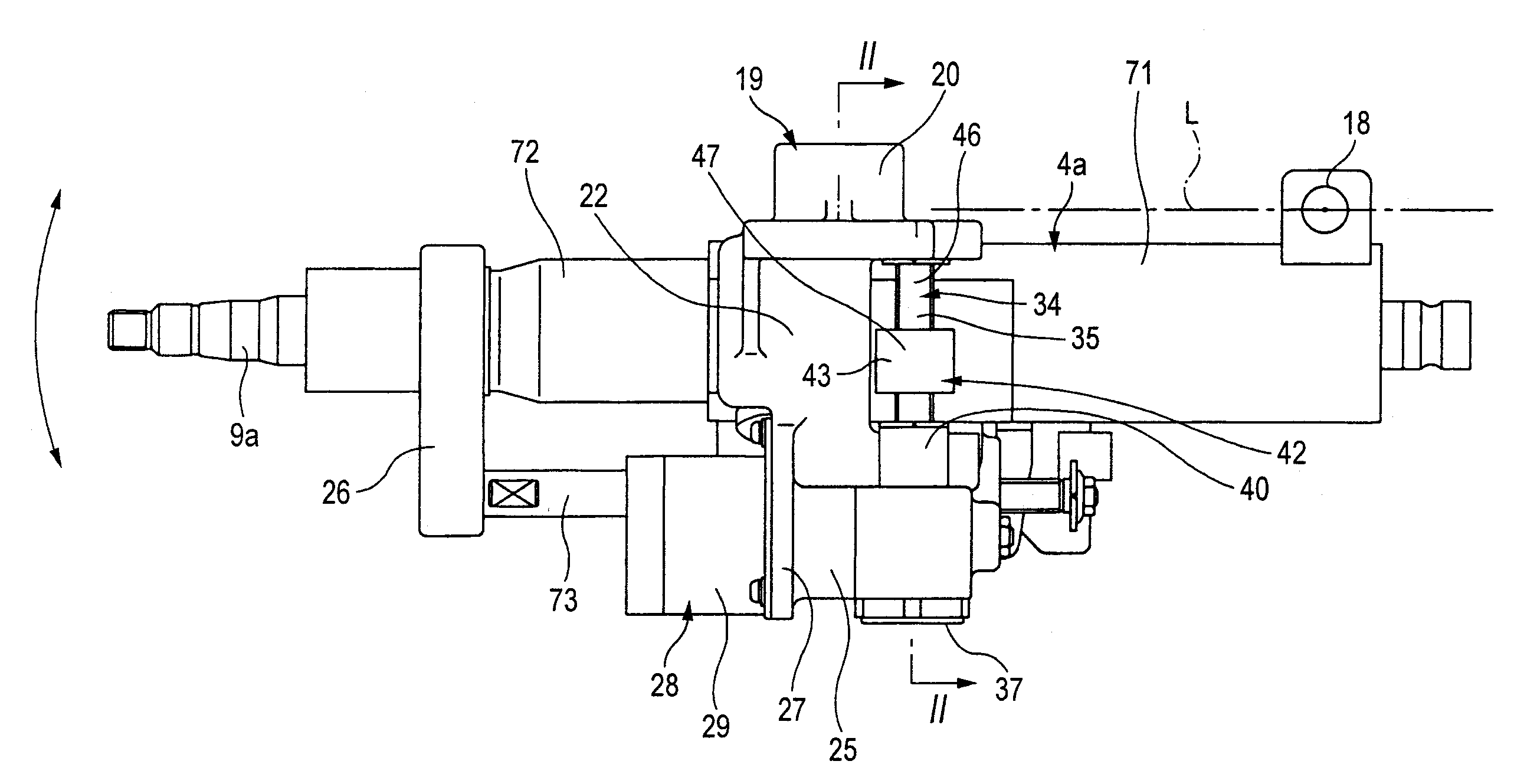
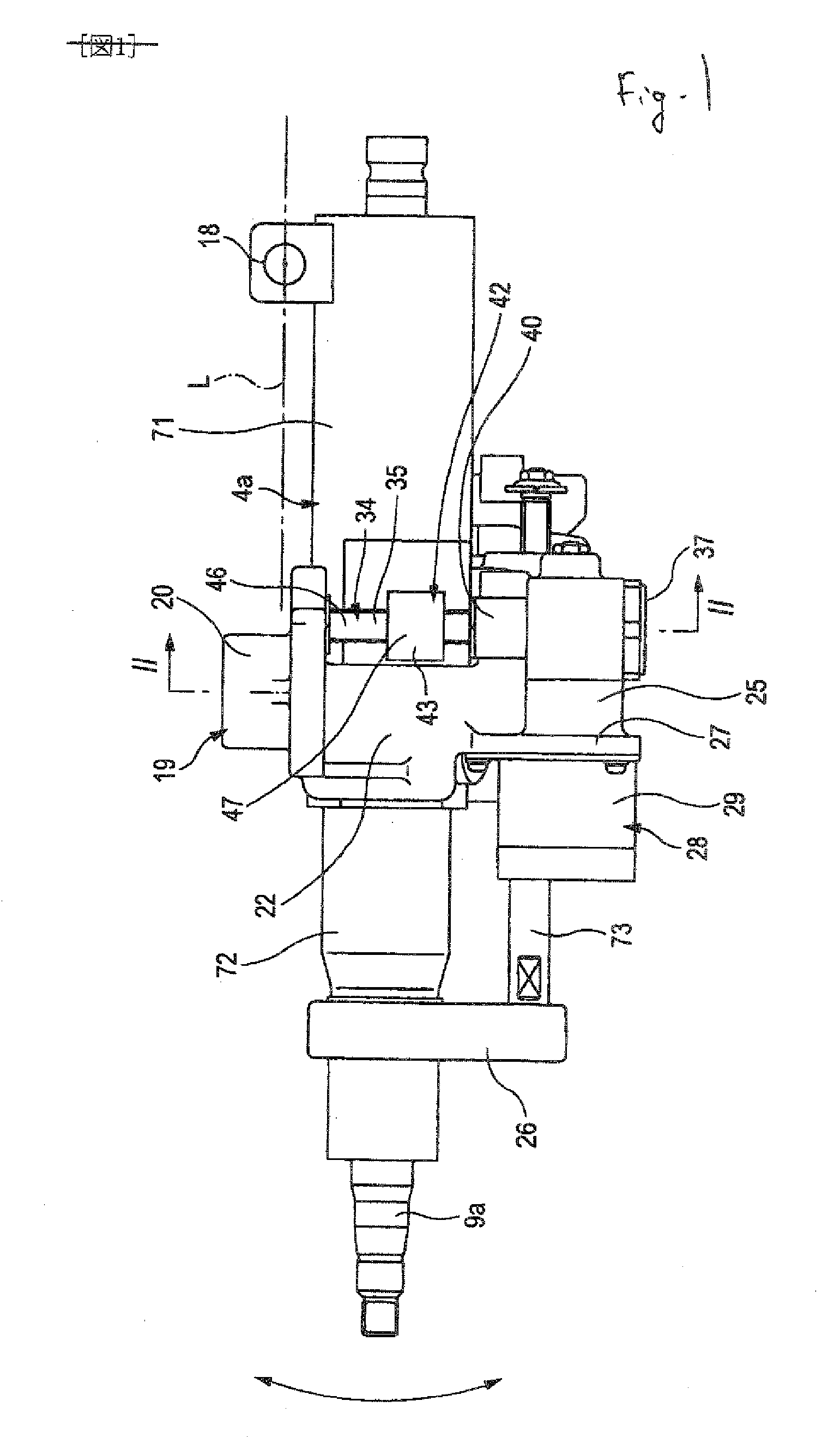
[0445]FIGS. 1 to 7 respectively show a tilt type electric steering apparatus according to an embodiment 1 of the invention, which corresponds to the first, second and fifth aspects of the invention. By the way, in FIGS. 1, 5 to 7, the front and rear sides of a vehicle body are reversed when compared with the structure shown in FIG. 15. That is, in FIGS. 1, 5 to 7, the right side of these figures shows the front side of the vehicle body, whereas the left side thereof shows the rear side of the vehicle body. In the present embodiment, the tilt type electric steering apparatus is structured such that, as shown in FIG. 1, a steering shaft 9a with a steering wheel 1 (see FIG. 15) fixed to its rear end portion (in FIG. 1, the left end portion) is rotatably supported on the inside of a steering column 4a which is supported on the vehicle body. The front end portion (in FIG. 1, the right end portion) of this steering shaft 9a is connected through a universal joint and an intermediate shaft ...

embodiment 2

[0461]Next, FIG. 8 shows an embodiment 2 which corresponds to the first, second, fourth and fifth aspects of the invention. In the present embodiment, to the outer surfaces of a pair of side wall portions 47 and 47 respectively provided on the width-direction (in FIG. 8, in the right and left direction) two end portions of a nut holder 43, there are fixed the base end portions (in FIG. 8, the right end portions) of a pair of shaft portions 53 and 53a. These two shaft portions 53 and 53a are situated coaxially with each other. The base end portion of an L-shaped arm portion 55 is fixed to the width-direction one side (in FIG. 8, the right side) of the outer peripheral surface of a steering column 4a that is shifted with respect to the nut holder 43 to one side thereof in the longitudinal direction (in FIG. 8, in the front and back direction). The leading end portion of the arm portion 55 is bent toward the nut holder 43 side and, in the inner surface (in FIG. 8, the left side surface...

embodiment 3

[0464]Next, FIG. 9 shows an embodiment 3 which also corresponds to the first, second, fourth and fifth aspects of the invention. According to the present embodiment, in the above-described embodiment 2 shown in FIG. 8, a shaft support bracket 58 is fixed through another column member 57 which is fixed to such portion of the steering column 4a (see FIG. 1 and the like) that not only exists on one side (in FIG. 9, on the right side) in the width direction of the outer peripheral surface of the steering column 4a but also is shifted with respect to the nut holder 43 toward the front side (in FIG. 9, on the upper side) thereof. This shaft support bracket 58 has a crank-like shape and includes a pair of flat plate portions 59, 59 extending parallel to each other, and a connecting portion 60 which connects together these two flat plate portions 59, 59. The two flat plate portions 59 and 59 are respectively bent in the mutually reversed directions with respect to the connecting portion 60....


PUM


Abstract

Both ends of a screw shaft 35 are supported on a vehicle body side bracket 19 so that only rotation is allowed. The screw shaft 35 is rotated by an electric motor 28. A nut member 44 is threadedly engaged with an intermediate portion of the screw shaft 35. The nut member 44 is held on inside of a nut holder 43. The nut holder 43 and nut member 44 are allowed to be shifted each other in longitudinal direction of the nut holder 43 which is perpendicular to both the shaft portion extending parallel to oscillation center axis of a steering column 4a and the axial direction of the screw shaft 35. The nut holder 43 is supported on the steering column 4a so as to be rotated about the shaft portion of the nut holder 43 relative to the steering column 4a.

Description

TECHNICAL FIELD[0001]The present invention relates to a steering apparatus which can adjust the tilt position and / or telescopic position of a steering wheel using an electric motor as a power source.BACKGROUND ART[0002]It is necessary to adjust the tilt position and / or telescopic position of a steering wheel using an electric motor as a power source according to the build and driving position of a driver. There is known a steering apparatus structured such that, by rotating an electric motor, a feed screw shaft is rotated to linearly move a feed nut threadedly engaged with the feed screw shaft, thereby adjusting the tilt position and / or telescopic position of a steering wheel.[0003]There is also conventionally known a tilt type electric steering column apparatus which adjusts the height position of a steering apparatus by driving an electric motor based on a switch operation. For example, FIG. 15 shows a tilt type electric steering apparatus disclosed in the patent reference 1. This...

Claims


Application Information

Patent Timeline
IPC IPC(8): B62D1/18
CPCB62D1/181
Inventor IWAKAWA, MASATOCHIKARAISHI, KAZUOTATEWAKI, OSAMU
Owner NSK LTD
Why Eureka
Try Eureka