U Shaped Cooler

a cooler and u-shaped technology, applied in the direction of exhaust gas recirculation, non-fuel substance addition to fuel, stationary tubular conduit assemblies, etc., can solve the problems of undesirable gas cooling and not desirable under all conditions

Inactive Publication Date: 2008-09-18
SENIOR INVESTMENTS
View PDF4 Cites 32 Cited by
  • Summary
  • Abstract
  • Description
  • Claims
  • Application Information

AI Technical Summary

Problems solved by technology

Further, there are applications where a hot gas inlet and a cooled gas outlet need to be in close proximity, due to space constraints.
Under some circumstances, heat exchange may be required, but under other circumstances it may be undesirable.
However, cooling the exhaust gas is not desirable under all conditions.
When gas is being transported through the bypass conduit, it is undesirable for the gas to be cooled.

Method used


Image

  • U Shaped Cooler
  • U Shaped Cooler
  • U Shaped Cooler

Examples


Embodiment Construction

[0048]In the following description numerous specific details are set forth in order to provide a thorough understanding. It will be apparent however, to one skilled in the art, that the present invention may be practiced without limitation to these specific details. In other instances, well known methods and structures have not been described in detail so as not to unnecessarily obscure the description.

[0049]Specific embodiments according to the present invention aim to utilize the positive features of a plate type U shaped cooler whilst addressing the design and manufacture problems of known plate type U shaped coolers.

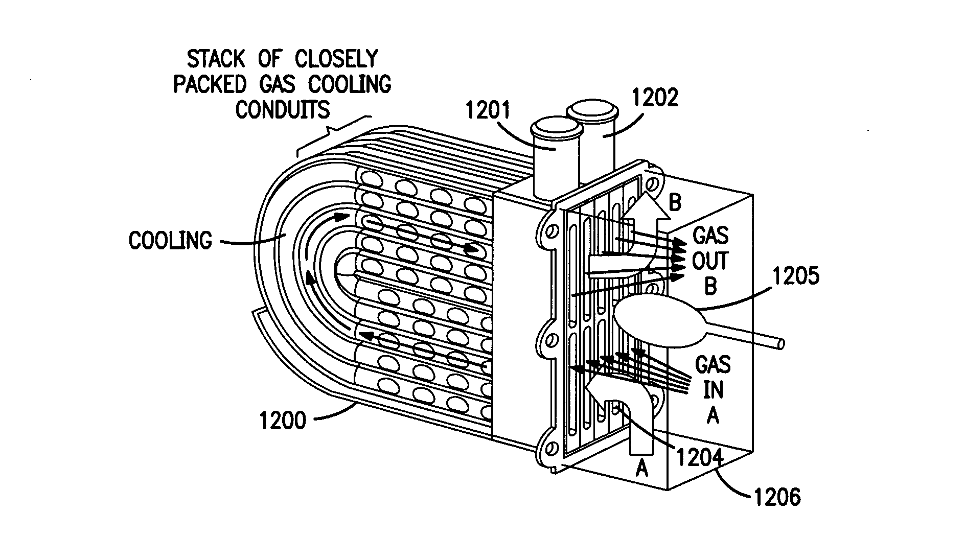
[0050]Referring to FIG. 1 herein, there is illustrated schematically a “U” shaped cooler according to a first specific embodiment of the present invention. The cooler comprises a “U” shaped canister 1200 having an inlet port 1201 for inlet of cooling fluid and an outlet port 1202 for outlet of the cooling fluid, such that the cooling fluid can flow throughout the can...


PUM

PropertyMeasurementUnit
lengthaaaaaaaaaa
thermal growthaaaaaaaaaa
shapeaaaaaaaaaa

Abstract

An exhaust gas re-circulation cooler device comprises at least one cooling plate, said cooling plate comprising an upper plate wall and a lower plate wall; said upper and lower plate walls defining a plurality of gas passages which have a gas inlet at a first end of cooling plate and a gas outlet at said first end of said cooling plate; each said passage directing a gas flow between said inlet and said outlet and along a length of said plate; and said plate being sealed so as to be gas tight along a length of said plate, and at a second end of said plate.

Description

FIELD OF THE INVENTION[0001]The present invention relates to gas heat exchangers, and particularly, although not exclusively, to exhaust gas re-circulation coolers for use in automotive applications.BACKGROUND TO THE INVENTION[0002]There are many applications in which it is desirable to use gas heat exchangers. These include applications where it is desirable to cool down a gas, for example, in exhaust gas re-circulation (EGR) coolers. Further, there are applications where a hot gas inlet and a cooled gas outlet need to be in close proximity, due to space constraints.[0003]Under some circumstances, heat exchange may be required, but under other circumstances it may be undesirable. For example, in cold engine conditions, it may be desirable not to cool the gas in order to aid more rapid heating of the engine, but under hot engine conditions, it may be desirable to cool the gas. Such an application includes an exhaust gas re-circulation circuit.[0004]Exhaust gas re-circulation is a me...

Claims


Application Information

Patent Timeline
Patent Type & Authority Applications(United States)
IPC IPC(8): F28F3/04F28D7/06B23P15/26
CPCB21D53/04F02M25/0728F02M25/0736F02M25/0737F28D7/0041Y10T29/49359F28D21/0003F28F3/044Y02T10/121F28F2255/10F28D7/1692F28F2250/102F02M26/25F02M26/31F02M26/32F28D9/0006F28D9/0081F28F3/08
Inventor PENNY, CHARLESNASH, CLAIRETAYLOR, MICHAELFAIRHURST, STEVENDOWNS, PAUL
Owner SENIOR INVESTMENTS
Why Eureka
Try Eureka