Image forming apparatus and method for controlling the same

a technology of image forming apparatus and control method, which is applied in the direction of electrographic process apparatus, printing, instruments, etc., can solve the problems of color misregistration problem and possible multi-factor problem, and achieve the effect of reducing color misregistration

Active Publication Date: 2008-09-18
CANON KK
View PDF10 Cites 21 Cited by
  • Summary
  • Abstract
  • Description
  • Claims
  • Application Information

AI Technical Summary

Benefits of technology

[0009]Embodiments of the present invention are provided to overcome the above-described drawbacks of the related technology. Specifically, the present invention provides a technique for reducing color misregistration occurring during color image formation under a wider range of conditions.
[0011]According to another aspect of the present invention, a color image forming apparatus includes a plurality of laser beam generating units corresponding to a plurality of colors, a plurality of photosensitive members, a plurality of developing units, and a detecting unit. Each of the laser beam generating units is configured to emit a laser beam based on image data output from an image data generating unit. The plurality of photosensitive members is configured to be exposed by optical scanning performed by the plurality of laser beam generating units and have respective electrostatic latent images formed thereon. The plurality of developing units is configured to develop the respective electrostatic latent images formed on the plurality of photosensitive members. The detecting unit is configured to read an image of a color misregistration detection pattern for each color formed by irradiation with a laser beam from the plurality of laser beam generating units and detect an amount of color misregistration, the amount of color misregistration being a relative positional displacement between the colors. The color image forming apparatus is operable in a plurality of operation modes including a first operation mode in which an optical scanning speed is a first scanning speed and a second operation mode in which the optical scanning speed is a second scanning speed lower than the first scanning speed. The plurality of laser beam generating units perform scanning in a first scanning direction on a first color and scanning in a second scanning direction on a second color, the first scanning direction being different from the second scanning direction. A delay time from detection of a synchronization signal for synchronizing image writing timing in a main scanning direction in image formation to reception of the image data output from the image data generating unit in response to the detected synchronization signal by the plurality of laser beam generating units occurs. To correct color misregistration using the same amount of correction of color misregistration based on the amount of color misregistration detected by the detecting unit in both the first operation mode and the second operation mode, at least one of the plurality of laser beam generating units emits a laser beam with image writing timing that enables a difference between delay color misregistration in the first operation mode and delay color misregistration in the second operation mode to be reduced, the difference being defined by an image writing position corresponding to the length of the delay time in scanning performed in the first scanning direction and an image writing position corresponding to the length of the delay time in scanning performed in the second scanning direction.

Problems solved by technology

With this, color misregistration (a problem in which images of different colors that should be formed in the same position are formed in different positions on a recording material) resulting from a plurality of factors may occur.
This problem is present especially in a tandem color image forming apparatus, which includes the same numbers of developing units and photosensitive drums as coloring materials and sequentially transfers images for different colors onto an intermediate transfer member or a recording medium.
However, the known technique cannot be applied to an apparatus that is operable in modes for different scanning speeds and that can perform scanning for a reference color (first color) and scanning for another color (second color) in different scanning directions, so the color misregistration problem still remains.

Method used


Image

  • Image forming apparatus and method for controlling the same
  • Image forming apparatus and method for controlling the same
  • Image forming apparatus and method for controlling the same

Examples


first embodiment

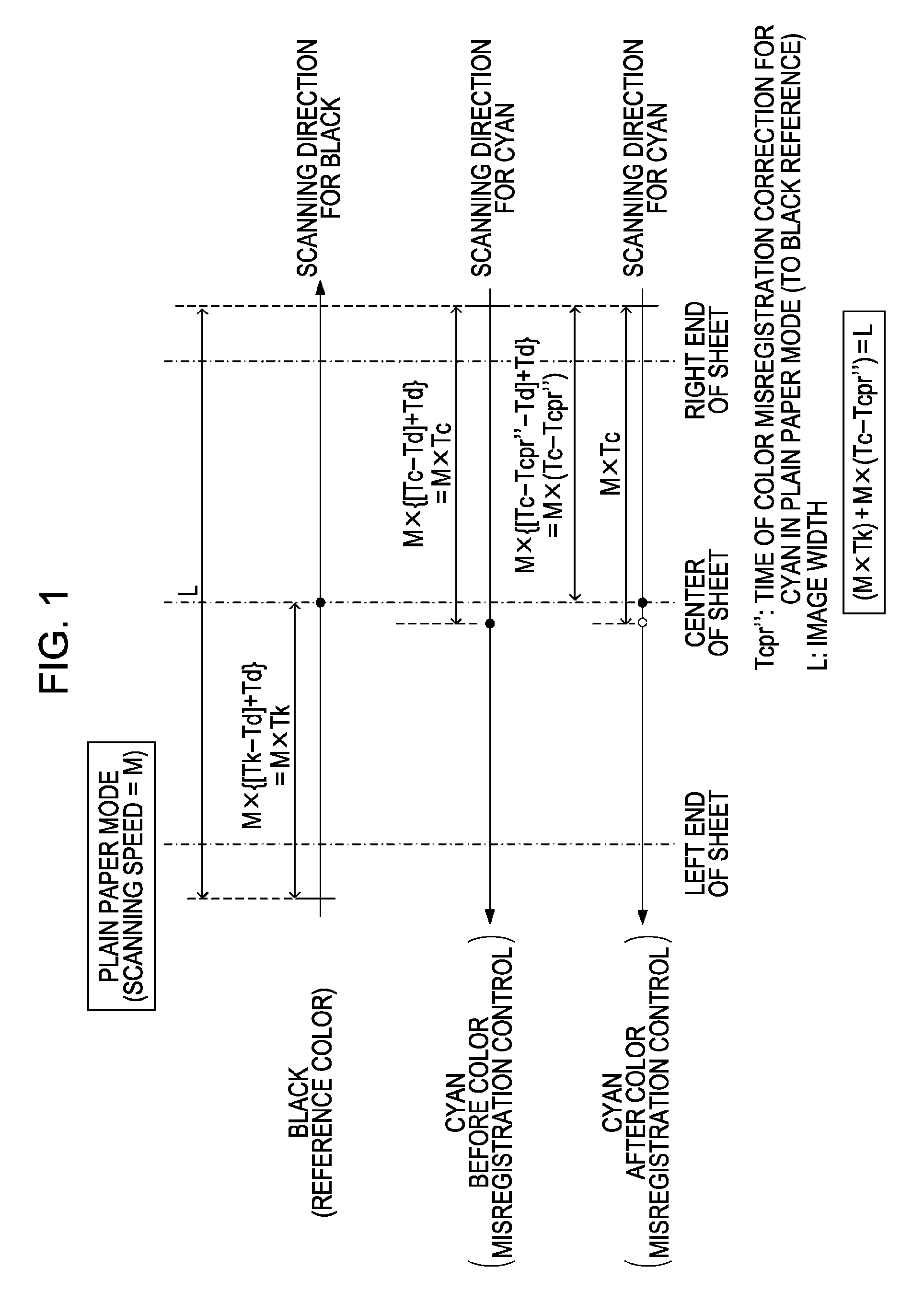
[0036]An image forming apparatus according to a first embodiment of the present invention will be described below. The image forming apparatus according to the present embodiment is a color printer that can change a scan direction of a laser beam in the main scanning direction and can also change an optical scanning speed in response to a condition (mode). The printer corrects color misregistration on the basis of the amount of delay from the input of a beam detection signal from a laser beam generating unit to, through the generation of image data, the input of the image data into the laser beam generating unit. Specifically, in response to this amount of delay, the time when image data is generated is controlled.

Apparatus Configuration

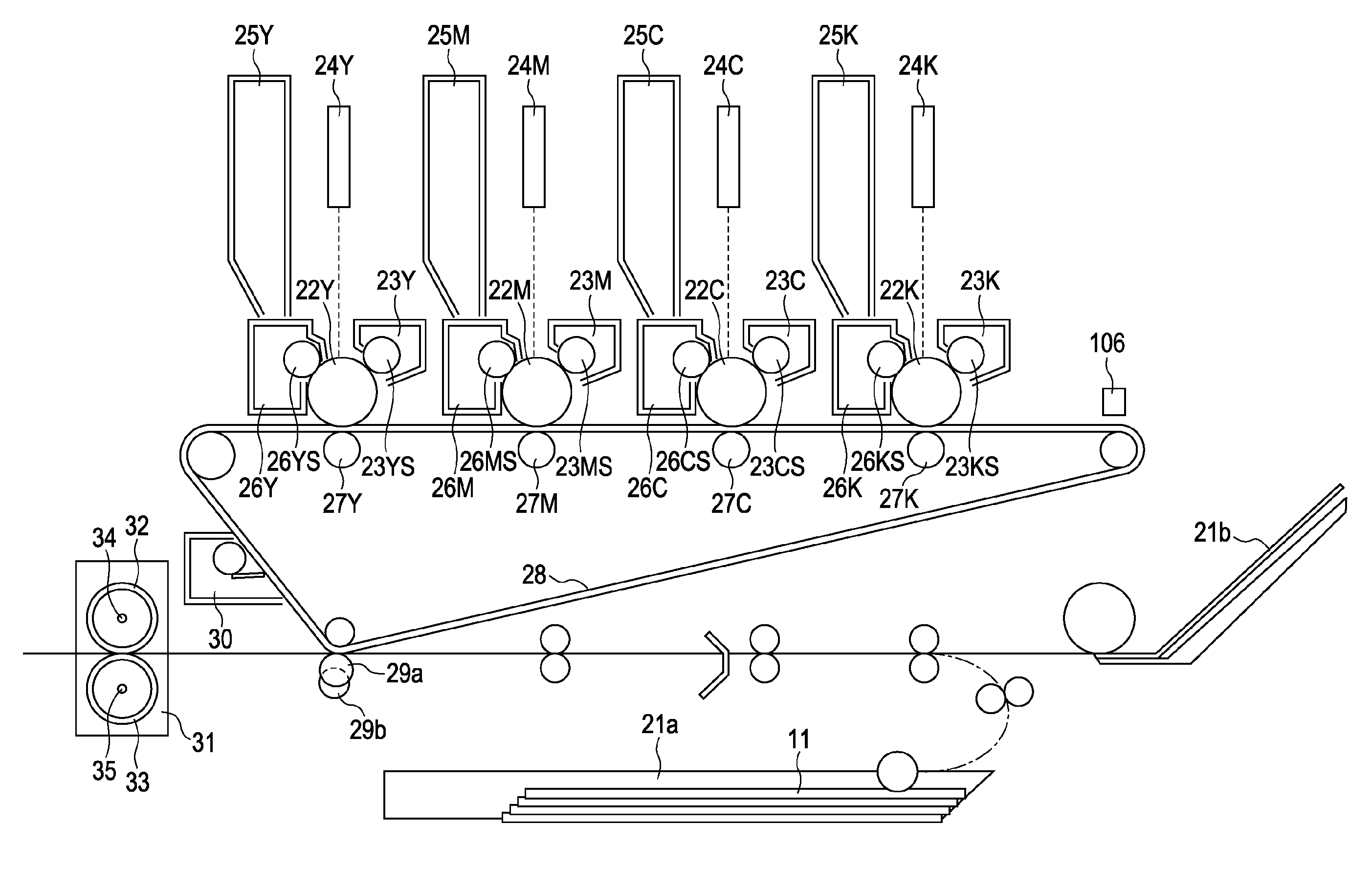
[0037]FIG. 2A is a cross-sectional view of a tandem color printer that uses an intermediate transfer member 28. The tandem color printer is an example of an electrophotographic color image forming apparatus. The printer includes image forming units c...

second embodiment

[0119]A color printer according to a second embodiment will now be described. In the first embodiment, the transmission delay time Td from output of a laser beam detection signal from the laser beam generating unit 1001 to input of an image data signal into the laser beam generating unit 1001 is measured by a measuring device (e.g., an oscilloscope) and stored in the memory 1004 in advance. In contrast, in the second embodiment, correction control of color misregistration (formation of a color misregistration detection pattern) is performed in each of the print modes, and the transmission delay time Td obtained by calculation from the performance of the correction control is stored in the memory 1004. Control executed after the transmission delay time Td is read from the memory 1004 is substantially the same as in the first embodiment.

[0120]As previously described with reference to FIG. 12, in a case where the scanning direction for the reference color and the scanning direction for...

third embodiment

[0126]A color printer according to a third embodiment will now be described. In the first embodiment, the transmission delay time Td from output of a laser beam detection signal from the laser beam generating unit 1001 to input of an image data signal into the laser beam generating unit 1001 is measured by a measuring device (e.g., an oscilloscope) and stored in the memory 1004 in advance. However, the delay time in a transmission path is changed with time by deterioration of an electric device (not shown) or other causes. To address this, in the third embodiment, a transmission delay detecting unit configured to detect the transmission delay time and serving as a delay-amount detecting unit is provided. The result of detection of the amount of delay is stored in the memory 1004, and the stored transmission delay time is read when needed to correct the time when image data is formed.

[0127]FIG. 18 illustrates the details of a controller that controls recording of an electrostatic lat...


PUM


Abstract

An image of a color misregistration detection pattern is formed, and the amount of color misregistration is detected by reading of the pattern image. The amount of color misregistration detected by a detecting unit and the delay time from the time when image data is requested to the time when the image data is output are stored. The color misregistration is corrected based on the stored delay time and amount of color misregistration.

Description

BACKGROUND OF THE INVENTION[0001]1. Field of the Invention[0002]The present invention relates to a technique for reducing color misregistration for use in an image forming apparatus.[0003]2. Description of the Related Art[0004]The speed at which an image is formed in recent color image forming apparatuses is becoming increasingly higher. With this, color misregistration (a problem in which images of different colors that should be formed in the same position are formed in different positions on a recording material) resulting from a plurality of factors may occur. A main factor is the accuracy with which an optical unit arranged for each color is mounted.[0005]This problem is present especially in a tandem color image forming apparatus, which includes the same numbers of developing units and photosensitive drums as coloring materials and sequentially transfers images for different colors onto an intermediate transfer member or a recording medium.[0006]FIGS. 19A and 19B are illustrat...

Claims


Application Information

Patent Timeline
Patent Type & Authority Applications(United States)
IPC IPC(8): G03G15/01
CPCG03G15/0131G03G2215/0161G03G2215/0129
Inventor SUGIYAMA, NORIKAZU
Owner CANON KK
Why Eureka
Try Eureka