
Array substrate and display device

An array substrate and display device technology, applied in the field of electronics, can solve problems affecting the imaging quality of liquid crystal displays, large differences in light transmittance, color shift of liquid crystal displays, etc.

Active Publication Date: 2015-05-27
BOE TECH GRP CO LTD +1
View PDF6 Cites 22 Cited by
  • Summary
  • Abstract
  • Description
  • Claims
  • Application Information

AI Technical Summary

Problems solved by technology

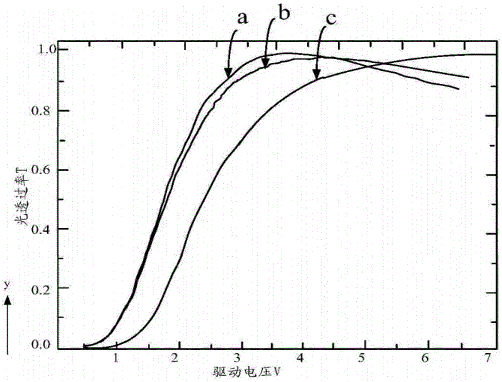
[0003] It can be seen that the curve a and the curve b basically coincide, especially, under the same driving voltage, the curve a and the curve b reach the peak almost at the same time, but the peak of the curve c is located on the right side of the peak of the curve a and the peak of the curve b , that is to say, under the same driving voltage, the light transmittance of the B pixel is quite different from the light transmittance of the R pixel and the G pixel. In this way, when the liquid crystal display panel is displaying, , due to the different light transmittances of the RGB three pixels, the color shift phenomenon of the liquid crystal display is caused, which affects the imaging quality of the liquid crystal display

Method used


Image

  • Array substrate and display device
  • Array substrate and display device
  • Array substrate and display device

Examples


Embodiment Construction

[0050] In the following description, for purposes of illustration rather than limitation, specific details, such as specific system architectures, interfaces, and techniques, are set forth in order to provide a thorough understanding of the present invention. It will be apparent, however, to one skilled in the art that the invention may be practiced in other embodiments without these specific details. In other instances, detailed descriptions of well-known devices, circuits, and methods are omitted so as not to obscure the description of the present invention with unnecessary detail.

[0051] In addition, the terms "first" and "second" are used for descriptive purposes only, and cannot be understood as indicating or implying relative importance or implicitly specifying the quantity of indicated technical features. Thus, a feature defined as "first" and "second" may explicitly or implicitly include one or more of these features. In the description of the present invention, unl...


PUM

PropertyMeasurementUnit
lengthaaaaaaaaaa
widthaaaaaaaaaa

Abstract

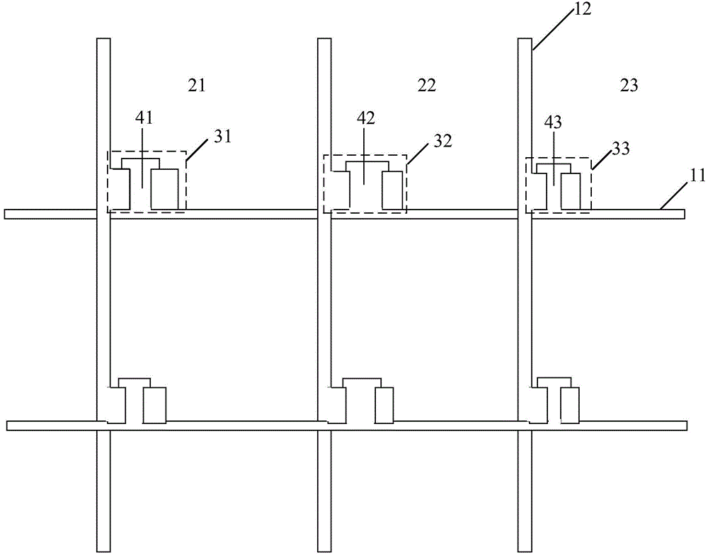
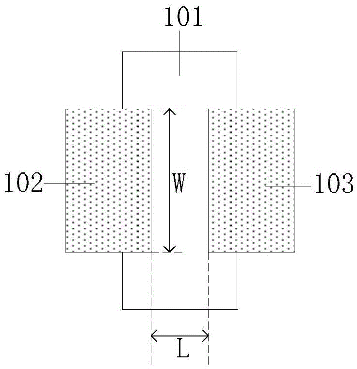
The embodiment of the invention provides an array substrate and a display device, relating to the technical field of electronics. The problem of color offset generated by a display device is reduced to a certain degree. According to the scheme, a first pixel unit corresponds to a red resistor and comprises a first TFT channel formed between the source and drain of a first TFT; a second pixel unit corresponds to a green resistor and comprises a second TFT channel formed between the source and drain of a second TFT; a third pixel unit corresponds to a blue resistor and comprises a third TFT channel formed between the source and drain of a third TFT; and the ratio of the width to length of the third TFT channel is higher than that of the second TFT channel, or the ratio of the width to length of the third TFT channel is higher than that of the first TFT channel. The scheme is used for the array substrate and the display device.

Description

technical field [0001] The present invention relates to the field of electronic technology, in particular to an array substrate and a display device. Background technique [0002] A Liquid Crystal Display (LCD) is mainly composed of a TFT array substrate and a color filter substrate. Among them, R (red) pixels and G (green) pixels are arranged on the liquid crystal display after the TFT array substrate and the color filter substrate are boxed together. and B (blue) pixels, where, as figure 1 As shown, that is, the VT curve (ie, the driving voltage-light transmittance change curve) of the R pixel is a; the VT curve of the G pixel is b; the VT curve of the B pixel is c. [0003] It can be seen that the curve a and the curve b basically coincide, especially, under the same driving voltage, the curve a and the curve b reach the peak almost at the same time, but the peak of the curve c is located on the right side of the peak of the curve a and the peak of the curve b , that is...

Claims


Application Information

Patent Timeline
Patent Type & Authority Applications(China)
IPC IPC(8): G02F1/1362G02F1/1368G02F1/1343H01L29/10H01L29/786
CPCG02F1/134309G02F1/136286G02F1/1368H01L29/1033H01L29/78696G02F1/133514H01L27/1222G02F1/136222G02F1/134327G02F2201/52H01L29/41733
Inventor 刘旭
Owner BOE TECH GRP CO LTD
Learn More