
Dynamic maintenance plan for an industrial robot

a robot and maintenance schedule technology, applied in the field of industrial robots, can solve the problems of many robot parts exchange, direct association of wear and tear of the unit, and the complexity of such technical systems gets increasingly higher, and achieve the effect of accurate and reliable maintenance schedules

Active Publication Date: 2008-09-18
ABB (SCHWEIZ) AG
View PDF8 Cites 33 Cited by
  • Summary
  • Abstract
  • Description
  • Claims
  • Application Information

AI Technical Summary

Benefits of technology

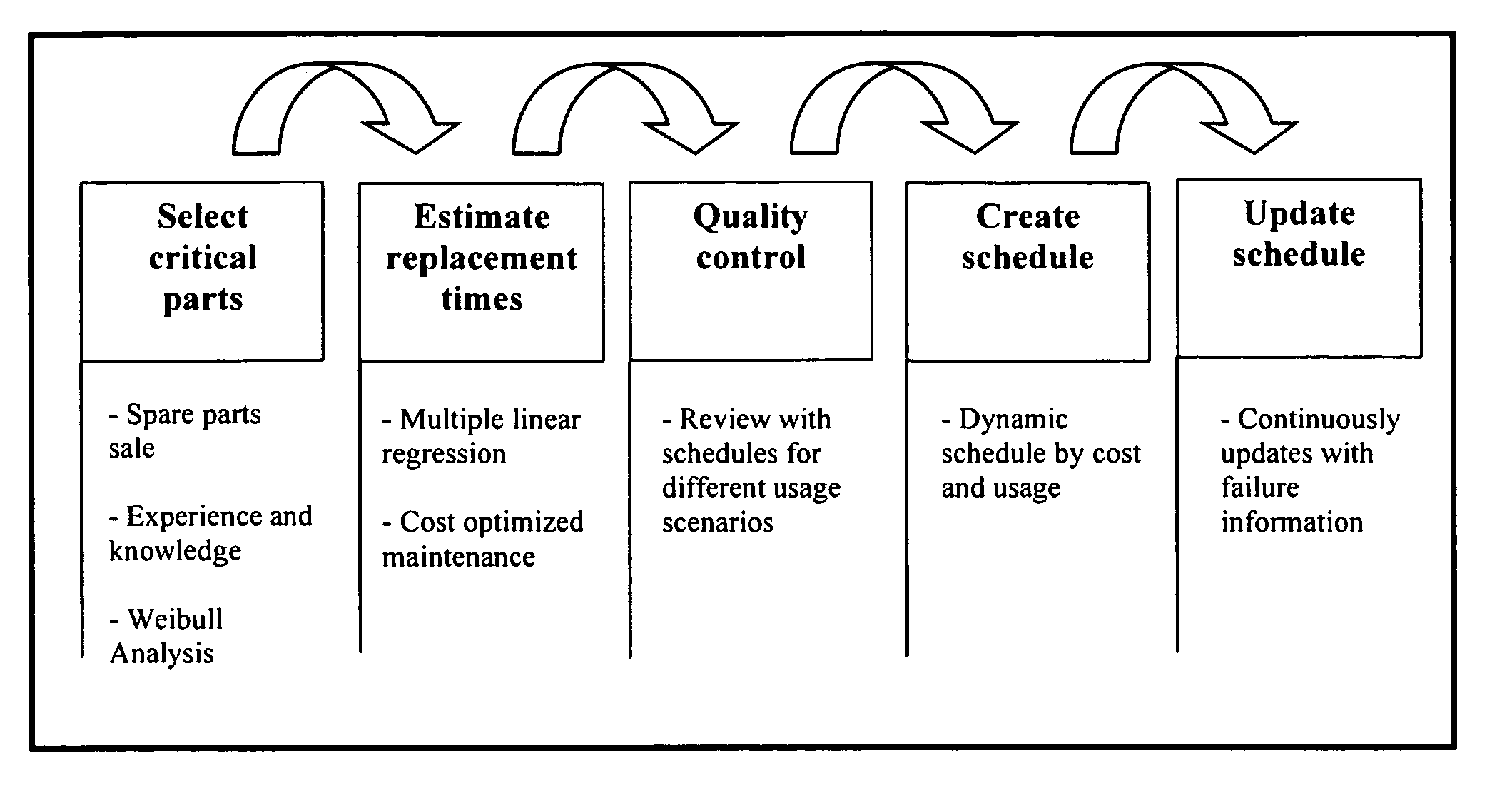
[0048]Both of the above listed ways for updating the dynamic maintenance scheduling tool require several work hours. It is possible to utilize a system with permanent improvements by use of the different methods in this report. In a system for automatic updates all robots included in the system are connected to the system. When a failure occurs the field service engineer has to report complete failure information to the system. All failures that are reported to the system will be stored in a database. The selection of the critical parts is performed by frequent Weibull analyses. Parts with failure rates that motivate preventive replacements are selected. Multiple linear regression analyses can then be performed continuously for generating updated function probabilities for the selected critical part. The replacement times in the original scheduling tool will then be updated with the latest replacement times that will be based on the result from the cost optimized maintenance analyses. The cost optimized maintenance analyses are based on the function probabilities from the continuously performed multiple linear regression analyses. The schedules will then always be based on the latest replacements. The more failures that are reported to the database, the more accurate and reliable the maintenance schedules will be.

Problems solved by technology

Therefore, usage of a static maintenance schedule for all robots in a population will cause many robots to have parts exchanged too soon, while other robots will have parts exchanged too late with undesired and costly production stops as a result.
Machinery, such as industrial robots and comparative technical systems are developed to manage more and more functions and the complexity of such technical systems gets increasingly higher.
The lifetime of the unit is directly associated with a level of wear.

Method used


Image

  • Dynamic maintenance plan for an industrial robot
  • Dynamic maintenance plan for an industrial robot
  • Dynamic maintenance plan for an industrial robot

Examples


example

[0110]Part Y is used in Robot Y. The program speed for the Robot is 1250 mm / s. It uses 60% of the envelope and the tool weight is 10 kg. The time for the replacement can then be estimated. The identification and graduation of the influence factors from a workshop is presented in the table. The approximated replacement time interval is from 20000 h for hard used parts to 40000 h for soft used parts.

ProgramEnvelopePartspeedusageTool weightPart Y4310 = No influence on Part Y's lifetime5 = Big influence on Part Y's lifetime

[0111]Maximum and minimum set up values for the three factors.

Envelope usageProgram speed (PS)(EU)Tool weight (TW)0 = 0 mm / s0 = 0%0 = 0 kg↓↓↓5 = 3000 mm / s5 = 100%5 = 16 kg

Estimation of the total wear factor for Part Y

Wear rate=Influence factor *% of max set up

WearratePS=4*(1250 / 3000)=1,667WearrateEU=3*(60 / 100)=1,8WearrateTW=1*(10 / 16)=0,625Sum=8=4,092

The totally achieved wear factor for Part Y is: (4.092 / 8)*5=2.5575. The example is illustrated in FIG. 6.

[0112]Processes...


PUM


Abstract

A method for establishing a dynamic maintenance scheduling tool for a specific part of a machinery based on condensed prior knowledge of the part of the machinery in a population of machineries. The scheduling tool is in turn used in a method for establishing a dynamic maintenance schedule for a specific part of a specific machinery, wherein parameters related to the usage, including relevant parameters representing factors influencing the lifetime of the specific parts, are utilized as input data to the dynamic maintenance scheduling tool for the specific part of the machinery, whereupon a dynamic maintenance schedule for the specific part of the specific machinery is achieved as output data from the scheduling tool. The method is in particular dedicated to industrial robot systems.

Description

TECHNICAL FIELD[0001]The present invention relates to methods for establishing maintenance schedules for a part of a machinery and for the machinery as a whole, in particular regarding an industrial robot.BACKGROUND OF THE INVENTION[0002]Nowadays preventive maintenance of a machinery is performed on occasions based on the size of a service agreement between a service department responsible for service of the machinery and a customer using the machinery. The amount of inspections per year can be settled in a service agreement. During inspections, one or several field service engineers are visiting the customer. The field service engineers perform preventive maintenance activities such as lubricating, cleaning, replacing packings, oil changing, etc. Normally, customers demand indications of a coming failure in order to give the field service engineer permission to replace parts. In many cases, service of the machinery, such as the service of an industrial robot, is performed in a reac...

Claims


Application Information

Patent Timeline
Patent Type & Authority Applications(United States)
IPC IPC(8): G06F19/00
CPCG05B23/0283G05B2219/32234G05B2219/32233G05B2219/32226Y02P90/02Y02P90/80
Inventor SJOSTRAND, NICLASBLANC, DOMINIQUELINDIN, ANDERS
Owner ABB (SCHWEIZ) AG
Learn More