Welded header for pressure transmitter

a transmitter and header technology, applied in the field of industrial processes, can solve the problems of preventing adequate advances in header miniaturization, large amount of heat generation, damage to electrical feedthrough connections,

Active Publication Date: 2008-09-25
ROSEMOUNT INC
View PDF22 Cites 16 Cited by
  • Summary
  • Abstract
  • Description
  • Claims
  • Application Information

AI Technical Summary

Problems solved by technology

A large amount of heat is generated in making deeply penetrating welds.
Such heat can damage the electrical feedthrough connections.
Heat damage, however, has prevented adequate advances in header miniaturization.

Method used


Image

  • Welded header for pressure transmitter
  • Welded header for pressure transmitter
  • Welded header for pressure transmitter

Examples


Embodiment Construction

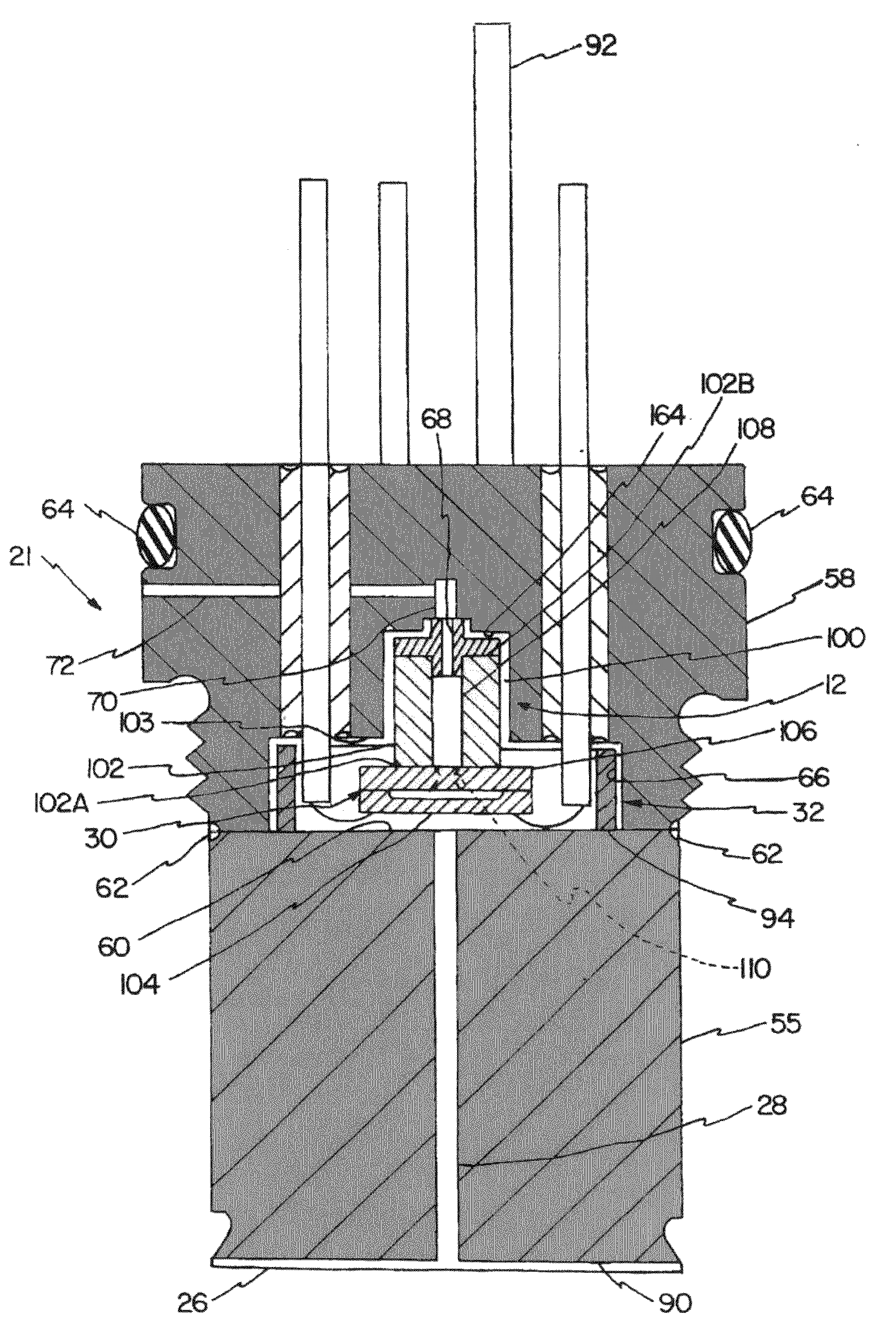
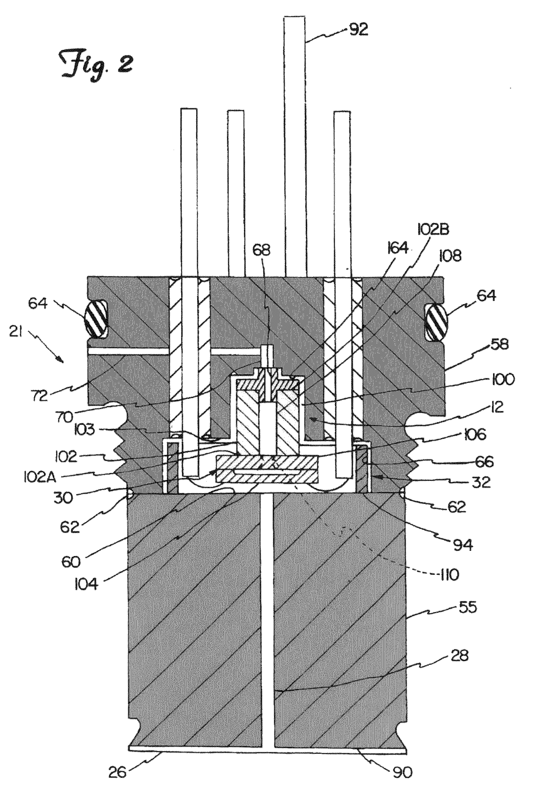
[0012]The present invention provides a configuration in a pressure transmitter in which the size of the header weld can be reduced. This reduces the amount of heat that is required to form the weld.

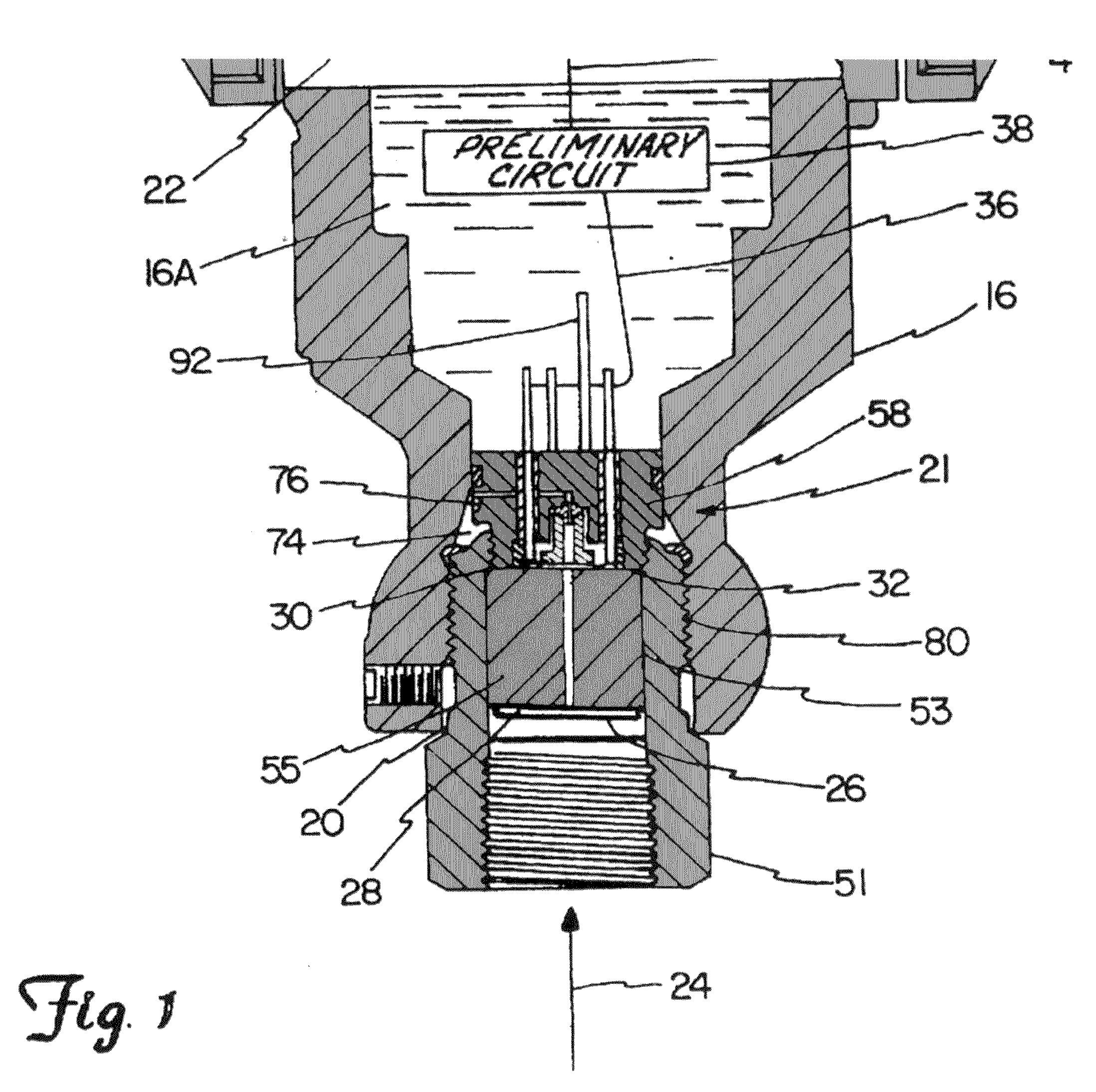
[0013]In the embodiments described below, a metal header is provided in a pressure transmitter with a stepped outer rim. The stepped outer rim has a header shelf between a larger rim diameter and a smaller rim diameter. The metal header includes a central plate with one or more feedthrough holes passing through the central plate. Metal pins, which are electrical connections, pass through the feedthrough holes. The metal pins are sealed to the holes with a glass-to-metal seal. The feedthrough holes are placed in close proximity to the outer rim.

[0014]The metal header fits into a stepped bore of a metal isolation wall of a pressure transmitter. The stepped bore includes a bore shelf. The stepped outer rim is welded to the stepped bore with one or more shallow welds to provide a seal. When p...


PUM

PropertyMeasurementUnit
diameteraaaaaaaaaa
diameteraaaaaaaaaa
diameteraaaaaaaaaa

Abstract

A pressure transmitter comprises a metal wall separating a process pressure chamber from an electronics compartment. The metal wall has a stepped bore with a bore shelf facing the process pressure chamber. A metal header has a stepped outer rim with a header shelf that contacts the bore shelf. The metal header includes at least one electrical feedthrough with a glass-to-metal seal adjacent the stepped outer rim. A welded seal seals the stepped outer rim to the stepped bore.

Description

BACKGROUND OF THE INVENTION[0001]The present invention relates to industrial processes. More specifically, the invention relates to pressure transmitters used in such processes.[0002]In process pressure instruments, headers are used to pressure-isolate process pressure from electronic circuits while providing for electrical feedthrough connections between electronics which are at atmospheric pressure and a pressurized sensor. The term “header” as used in this application refers to a base that supports hermetically sealed, electrically insulated leads. Deeply penetrating metal welds are often used to seal header joints. The deep penetration of the weld helps ensure a hermetic seal at the weld. The weld also provides sufficient mechanical strength to prevent cracking at the weld.[0003]A large amount of heat is generated in making deeply penetrating welds. Such heat can damage the electrical feedthrough connections. To avoid heat damage to the electrical feedthrough connections, header...

Claims


Application Information

Patent Timeline
Patent Type & Authority Applications(United States)
IPC IPC(8): G01L9/04
CPCG01L19/003G01L19/0645G01L19/0084G01L19/0061
Inventor KLEVEN, LOWELL A.ROMO, MARK G.
Owner ROSEMOUNT INC
Why Eureka
Try Eureka