
Second stage regulator

a regulator and second stage technology, applied in the field of second stage regulators, can solve the problems of limiting the amount of air available to the diver, the diver had to stay near the surface, and the diver could only travel as far as the diving bell's air tube allowed, so as to achieve the effect of prolonging the dive tim

Inactive Publication Date: 2008-10-16
SIMMONS GEORGE
View PDF13 Cites 0 Cited by
  • Summary
  • Abstract
  • Description
  • Claims
  • Application Information

AI Technical Summary

Benefits of technology

[0011]The apparatus in accordance with the inventor's improved second stage regulator provides a second-stage SCUBA regulator that allows a diver to extend dive times by conserving air exhaled from anatomic dead space.

Problems solved by technology

The first recorded underwater breathing device was a hollow reed used as a snorkel, which had the disadvantage that the diver had to stay near the surface.
Diving bells followed shortly thereafter and used the same concept as hollow reeds, but had the disadvantage that the diver could only travel as far as the diving bell's air tube allowed.
In most SCUBA applications, the limiting factor for how long a diver can remain underwater is the amount of air available to the diver.
The current design of the automatic demand second-stage regulator suffers from inefficiencies for two reasons.
The chemicals used in such designs may cause harm to humans, so rebreathers are typically limited to specific types of military and professional applications.
The second inefficiency relates to the existence of anatomic dead space within the human body.
Thus, approximately thirty percent (30%) of air inhaled in a SCUBA system is not used, but is instead wasted.

Method used


Image

  • Second stage regulator
  • Second stage regulator
  • Second stage regulator

Examples


Embodiment Construction

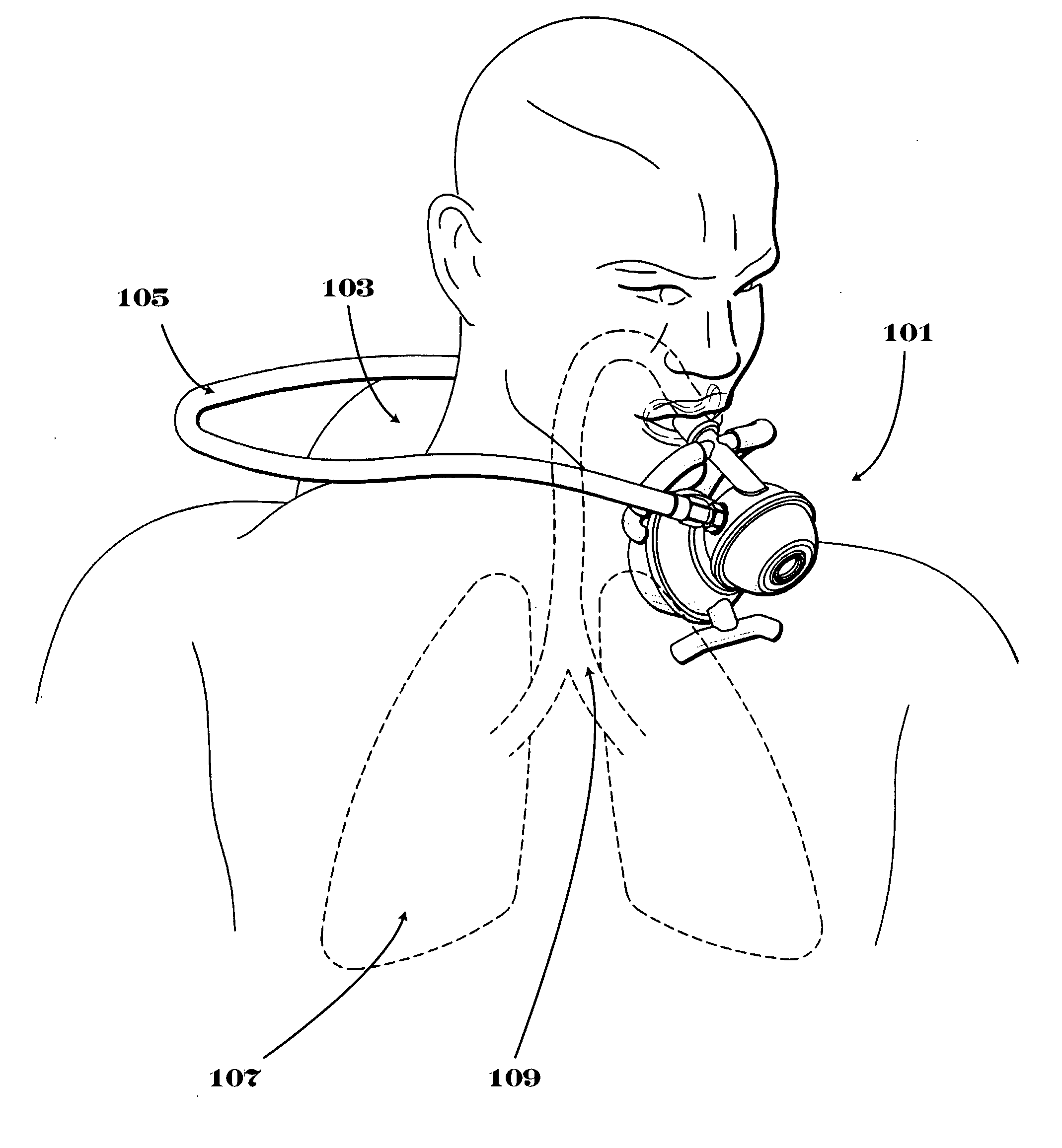
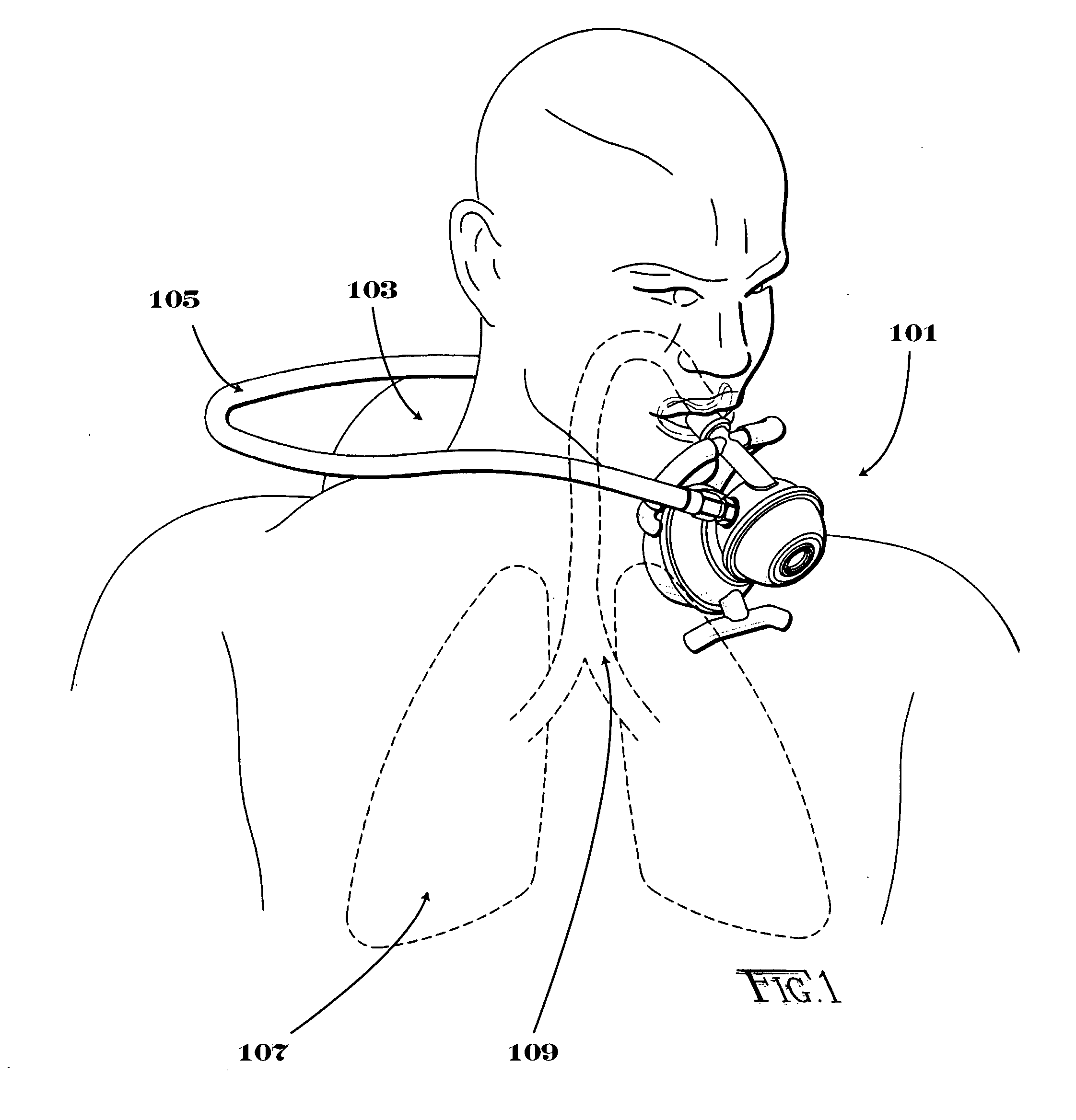
[0021]Referring now to FIG. 1, an improved second stage regulator 101 operates much like second stage regulators of the prior art. A diver attaches the improved second stage regulator to a first stage regulator (not shown) attached to an air tank 103 via hose 105. The first stage regulator and improved second stage regulator 101 generally operate to supply air on demand to the diver's lungs 107 at a usable pressure. The inventive step of the improved second stage regulator is that it conserves air exhaled from anatomic dead space 109 during the diver's normal respiratory cycle.

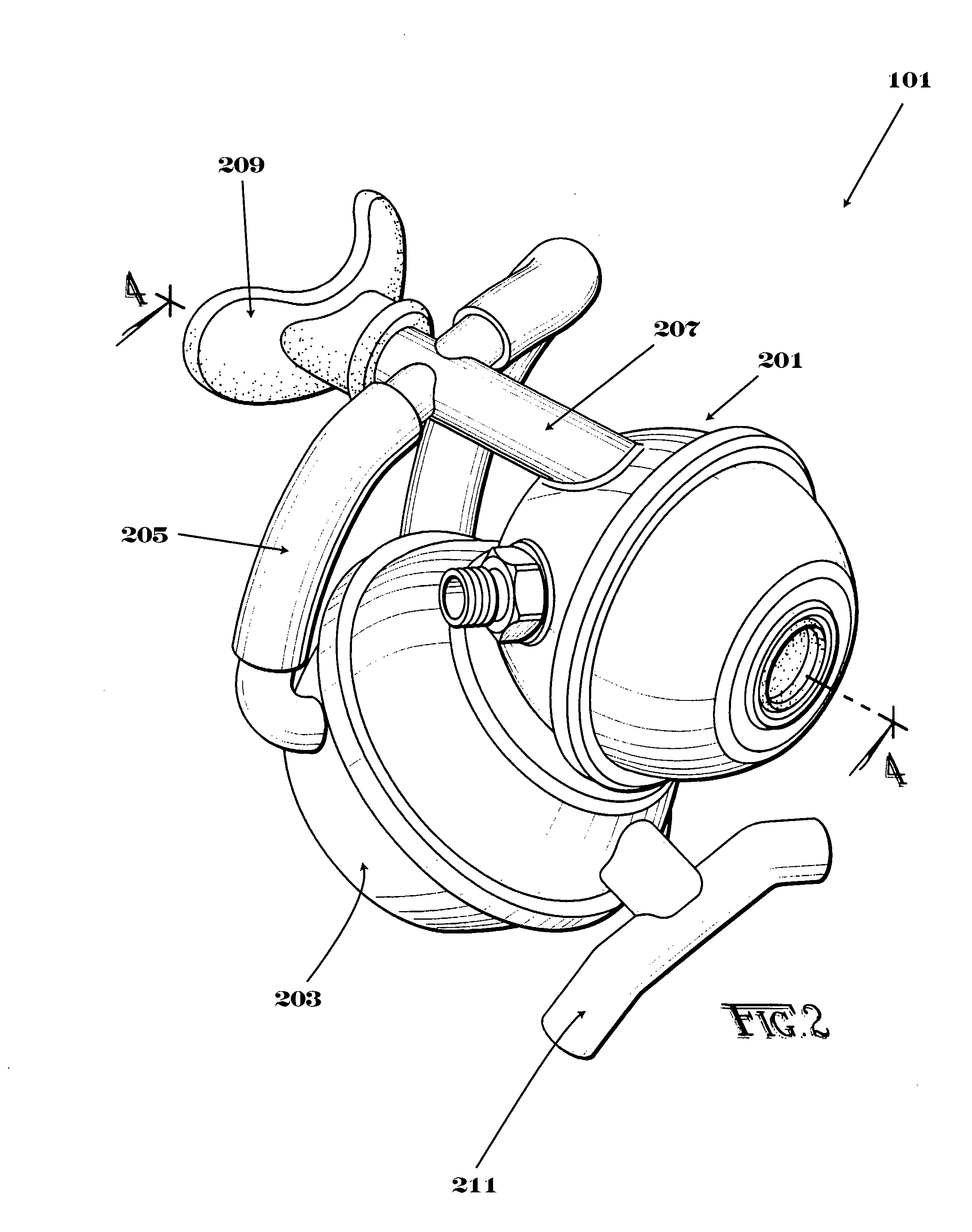
[0022]Referring now to FIG. 2, improved second stage regulator 101 comprises several additional components in addition to a demand valve housing 201. Conservation chamber 203 is connected to passageway 207 via one or more tubes 205. Tubes 205 serve as a conduit for air between mouthpiece 209 and conservation chamber 203. Passageway 207 may be elongated and may take many forms. Improved second stage regulator 1...


PUM


Abstract

An improved second stage regulator has a conservation chamber for conserving air exhaled by a diver from anatomic dead space. The conservation chamber is divided into two parts by a flexible diaphragm, which allows the conservation chamber to fill upon a diver's exhalation and recycles this air upon the diver's inhalation.

Description

CROSS REFERENCES[0001]None.GOVERNMENTAL RIGHTS[0002]None.BACKGROUND OF THE INVENTION[0003]Since ancient times, humans have recognized a need to prolong the time one can stay underwater in order to gather food, to collect precious seabome objects, or to engage in warfare. The first recorded underwater breathing device was a hollow reed used as a snorkel, which had the disadvantage that the diver had to stay near the surface. Diving bells followed shortly thereafter and used the same concept as hollow reeds, but had the disadvantage that the diver could only travel as far as the diving bell's air tube allowed. Diving bells were the sole form of underwater respiration for centuries, and thus there was long a need for a self-contained underwater breathing apparatus.[0004]In the 1800's, the first self-contained underwater breathing apparatuses (SCUBA) were built. These SCUBA designs generally took two forms: (1) a wet design, in which an air tank provides an air supply to the mouth and / o...

Claims


Application Information

Patent Timeline
Patent Type & Authority Applications(United States)
IPC IPC(8): A62B9/02
CPCB63C11/2227
Inventor SIMMONS, GEORGE
Owner SIMMONS GEORGE
Learn More