Electronic device

a technology of electronic devices and identification units, applied in the direction of burglar alarms, mechanical actuation of burglar alarms, instruments, etc., can solve the problems of easy breakage of chain locks, low and ineffective use of chain locks to lock projection apparatuses. , to achieve the effect of reducing the theft rate of electronic devices

Inactive Publication Date: 2008-10-16
CORETRONIC
View PDF10 Cites 5 Cited by
  • Summary
  • Abstract
  • Description
  • Claims
  • Application Information

AI Technical Summary

Benefits of technology

[0011]The present invention is directed to an electronic device, wherein an electronic device body is only activated by a corresponding remote unit, thus the theft rate of an electronic device is reduced by separately storing the electronic device body and the remote unit.
[0012]The present invention is directed to an electronic device, wherein the electronic device body is only activated when the electronic device body is connected to a corresponding cable. Therefore the theft rate of the electronic device body is reduced by separately storing the electronic device body and the cable.
[0015]In the present invention, the identification unit in the electronic device body identifies the tag of the remote unit. And when the identification signal transmitted from the tag is same as the identification code stored in the storage unit of the identification unit, and then the electronic device body is activated. Therefore, the present invention reduces the theft rate of an electronic device body by separately storing the electronic device body and the remote unit.

Problems solved by technology

However, although fancy and tiny electronic device has good portability, it is also likely to be stolen, therefore, at present the anti-theft design of an electronic device is also well considered.
However, among the above anti-theft technology, chain lock is very easily broken by thieves, so using chain lock to lock a projection apparatus is not so effective.
In addition, when a thief sees a projection apparatus with cipher lock, the thief usually steals the projection apparatus first and then try to crack the password of the cipher lock, therefore the anti-theft effectiveness is not so effectively good either.
In addition, for the projection apparatus with cipher lock, although users prevent the projection apparatus from turning on by simply taking away the keypad to lock the projection apparatus, however, when the keypad is taken away, the chip lock under the keypad of the projection apparatus is exposed.
Not only the appearance of the projection apparatus is not good, but also the chip lock is very easily damaged.
In addition, since a ceiling mount type projection apparatus is usually mounted on the ceiling, users usually can't easily reach the projection apparatus, so the ceiling mount type projection apparatus usually is controlled with remote control instead of being equipped with a keypad.
Therefore, because a chip lock is not easy to remove, so a chip lock cannot be used in a ceiling mount type projection apparatus.
Therefore design a chip lock on a projection apparatus does not reduce the theft rate effectively.

Method used


Image

  • Electronic device
  • Electronic device
  • Electronic device

Examples


first embodiment

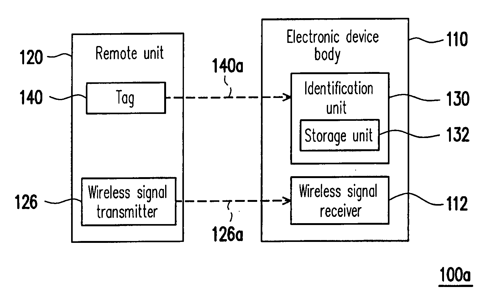
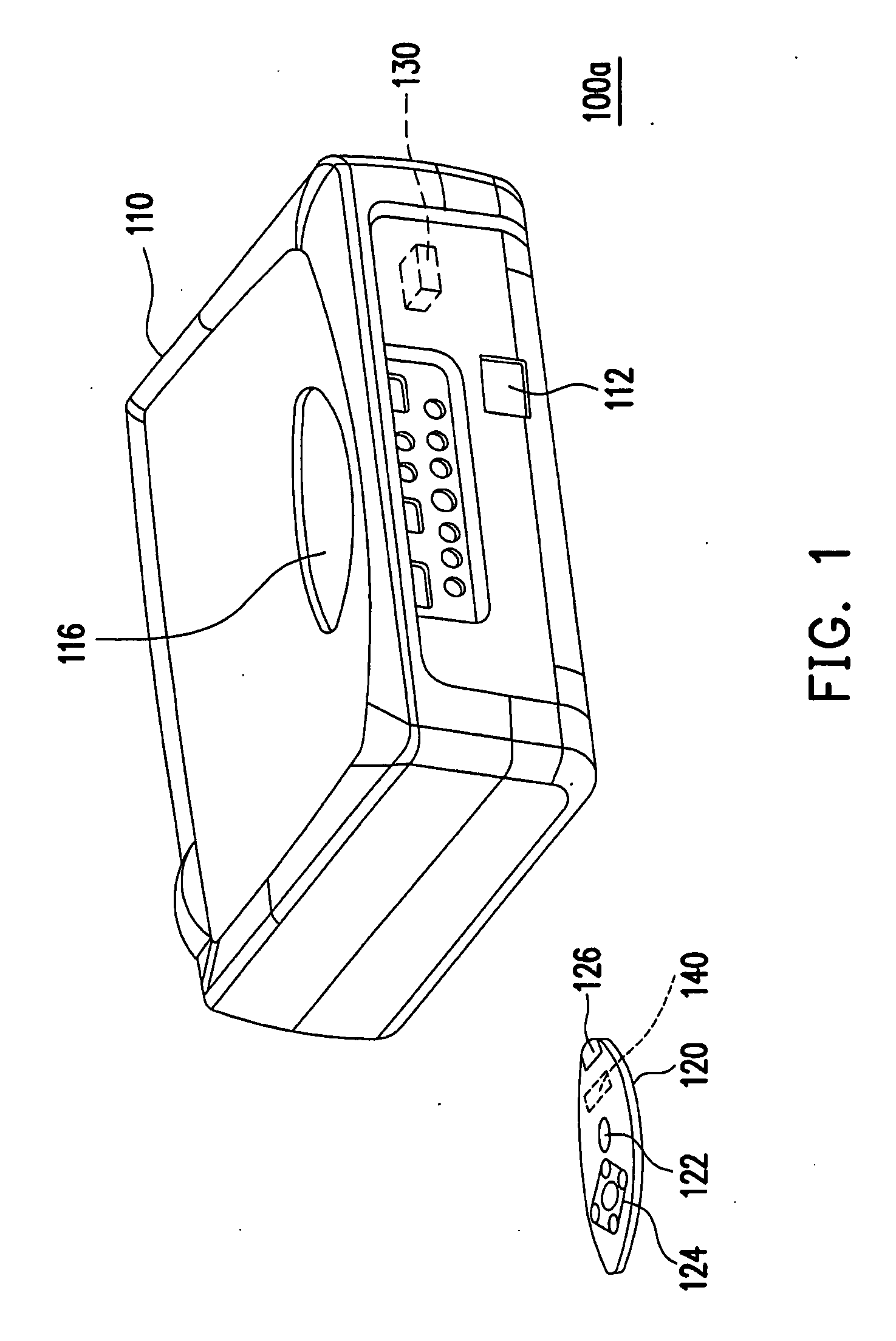
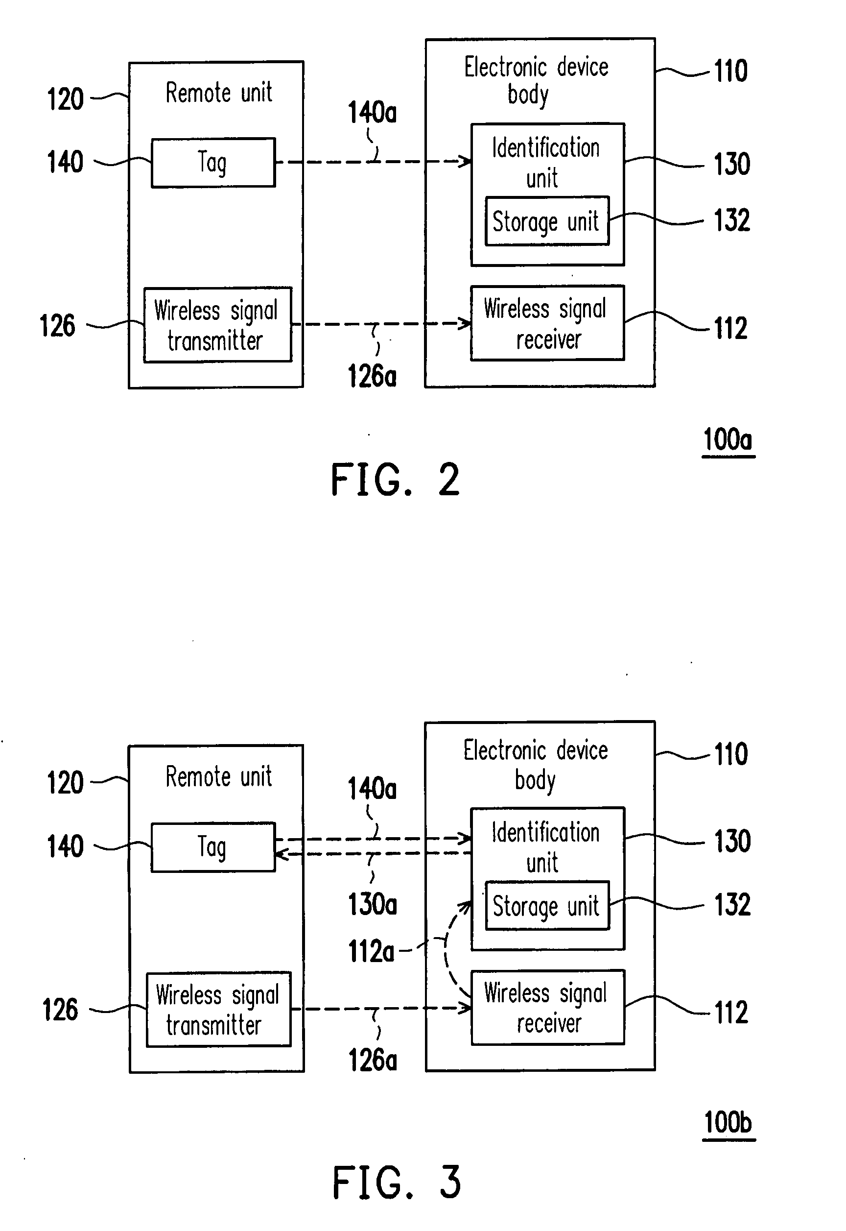
[0026]FIG. 1 is a perspective view of an electronic device according to the present invention. Referring to FIG. 1, an electronic device 100a includes an electronic device body 110, a remote unit 120, an identification unit 130 and a tag 140. The remote unit 120 comprises a first switch 122. The identification unit 130 is disposed in the electronic device body 110, and the tag 140 is disposed in the remote unit 120. When the remote unit 120 is close to the electronic device body 110 and the first switch 122 is turned on via for example a press method, the identification unit 130 is capable of identifying the tag 140 to activate the electronic device body 110.

[0027]Although the electronic device 100a shown in FIG. 1 is a projection apparatus, however the present invention is not limited there-to as such. For example, the electronic device 100a also includes electronic devices such as a notebook computer, a digital camera, a digital video camcorder and a DVD player and etc.

[0028]The i...

third embodiment

[0045]In the present embodiment, the electronic device 100d further includes a cable 150. The electronic device body 110 further comprises a first connector 118, and the cable 150 has a second connector 152, and the second connector 152 is capable of connecting to the first connector 118. Moreover, the identification unit 130 is disposed in the electronic device body 110 and is close to the first connector 118, and the tag 140 is disposed in the second connector 152. When the second connector 152 is connected to the first connector 118 and the second switch 114a is turned on by, for example, a press method, the identification unit 130 is capable of identifying the tag 140 to activate the electronic device body 110. The manner by which the identification unit 130 identifies the identification signal 140a is similar to that of the third embodiment, therefore it is not described again.

[0046]In addition, the first connector 118 is, for example, a power jack, and the second connector 152...

second embodiment

[0048]Referring to FIG. 6 and FIG. 8, when the second connector 152 is connected to the first connector 118, users also press the first switch 122 of the remote unit 120 to make the identification unit 130 identify the tag 140 to activate the electronic device body 110. The manner that the identification unit 130 identifies the identification signal 140a is similar to that of the second embodiment, therefore it is not described again.

[0049]Accordingly, before users activate the electronic device body 110 by pressing the first switch 122 or the second switch 114a, the corresponding second connector 152 has to be connected to the first connector 118 first, so that the identification unit 130 identifies the tag 140. Therefore, users just need to store the cable 150 in a safe place to reduce the theft rate of the electronic device 100d.

[0050]FIG. 9 is a block diagram of an electronic device with an active RF tag according to a fifth embodiment of the present invention. Referring to FIG...


PUM


Abstract

An electronic device including an electronic device body, a remote unit, an identification unit and a tag is provided. The remote unit has a first switch. The identification unit is disposed in the electronic device body, and the tag is disposed in the remote unit. When the remote unit is close to the electronic device body and the first switch is turned on, the identification unit is capable of identifying the tag to activate the electronic device body. Because the electronic device body is activated after the tag is identified by the identification unit, the invention is able to reduce the theft rate of the electronic device body by separately storing the electronic device body and the remote unit.

Description

CROSS-REFERENCE TO RELATED APPLICATION[0001]This application claims the priority benefit of Taiwan application serial no. 96205660, filed Apr. 10, 2007. All disclosure of the Taiwan application is incorporated herein by reference.BACKGROUND OF THE INVENTION[0002]1. Field of the Invention[0003]The present invention relates to an electronic device, and more particularly, relates to an electronic device with an identification unit.[0004]2. Description of Related Art[0005]Along with the advancement of science and technology, various electronic devices such as projection apparatus, notebook computer, digital camera, digital video camcorder, digital video disc player (DVD player) and etc are widely used. To meet the demand for portability, the electronic devices are designed to be light, small, compact and thin.[0006]However, although fancy and tiny electronic device has good portability, it is also likely to be stolen, therefore, at present the anti-theft design of an electronic device i...

Claims


Application Information

Patent Timeline
Patent Type & Authority Applications(United States)
IPC IPC(8): G08B13/14
CPCG08B13/1418
Inventor CHEN, JUNG-CHICHEN, CHE-HSUEHTENG, WEN-CHI
Owner CORETRONIC
Why Eureka
Try Eureka