Printing apparatus and conveying control method

a technology of conveying control and printing equipment, which is applied in the direction of printing, typewriters, other printing equipment, etc., can solve the problems of periodical variation in the conveying of printing medium, shape difference, distance between the printing medium and the print head,

Active Publication Date: 2008-10-16
CANON KK
View PDF9 Cites 31 Cited by
  • Summary
  • Abstract
  • Description
  • Claims
  • Application Information

AI Technical Summary

Benefits of technology

[0016]In the printing apparatus and the conveying control method that are provided with the above-described configuration, the correction is carried out in accordance with the actual amount of conveying the printing medium. As a result, the apparatus and the method can contribute to the achievement of the printing of high-quality images.

Problems solved by technology

Some of the various causes of such displacement deviation are: difference in shape amongst the nozzles of the print head; noise factors, such as the vibrations of the apparatus that occur while the printing is being carried out; and the distance between the printing medium and the print head.
Such difference in conveying amount results in a periodical variation in the conveying of the printing medium.
Accordingly, the printing apparatus thus produced becomes more expensive.
In this state, the flatness of the printing medium may not be secured.
As a consequence, fluctuations of not a small amount occur in the distance between the print head and the end portion that is not supported, and create a quite unstable state.

Method used


Image

  • Printing apparatus and conveying control method
  • Printing apparatus and conveying control method
  • Printing apparatus and conveying control method

Examples


first embodiment

2.1 First Embodiment of Printing-Medium Conveying Control

(1) Printing Method in First Embodiment

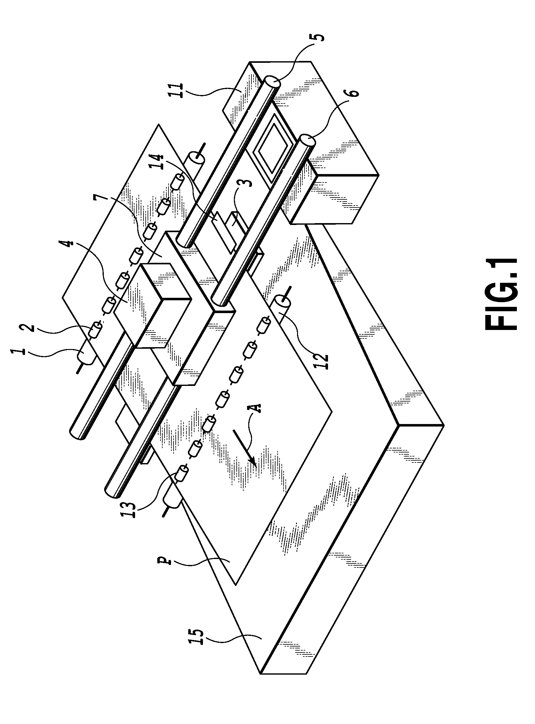
[0205]In a first embodiment of the control of conveying a printing medium, the printing on the front-end portion and on the rear-end portion of the printing medium P is carried out by reducing appropriately the range of nozzles to be used.

[0206]In some cases of the printing on the front-end portion or the rear end portion of the printing medium P, either one of the conveying roller 1 and the discharge roller 12 is not actually involved in the conveying of the printing medium P. FIGS. 37A and 37C illustrate examples of these cases. When the printing medium P is supported and conveyed by only one of the conveying roller 1 and the discharge roller 12 as in the above-mentioned cases, the flatness of the printing medium P is not secured at a sufficient level. As a result, the distance between the print head and the end portion that is not supported (hereafter, also referred to as “head-to-pape...

example 1

(3) Modified Example 1

[0241]As described above, in the front-end portion and the rear-end portion of the printing medium P, flatness of the printing medium P cannot always be secured while the printing medium P is being supported and conveyed by either the conveying roller 1 or the discharge roller 12 alone. That is why the printing on the front-end portion and on the rear-end portion in the first embodiment is carried out by reducing the range of nozzles to be used in printing. Note that the conveying of the printing medium P at that time is carried out without applying the correction value for eccentricity.

[0242]Incidentally, the printing on the front-end portion and on the rear-end portion is not the only occasion where the printing is carried out with a reduced range of nozzles to be used. For example, even the printing on the second area is sometimes carried out with a reduced range of nozzles to be used to achieve a high-quality printing. An example of such printing with a red...

example 2

(4) Modified Example 2

[0244]In the embodiment described above, the determination made on whether the eccentricity correction is carried out depends on an area where printing is going to be carried out. Here, the area is either an area that should be printed by using all the nozzles or an area that should be printed by using only a limited number of nozzles. The present invention, however, is not necessarily carried out in this way. In a possible alternative, the determination made on whether the eccentricity correction is carried out depends on whether the printing apparatus is set in a printing mode of using all the nozzles or in a printing mode of using a limited number of nozzles.


PUM


Abstract

Provided are a printing apparatus and a conveying-error controlling method capable of printing a high-quality image by correction reflecting the conveying amount of a printing medium. A provided inkjet printing apparatus prints images by printing scans for actual printing and by conveying the printing medium with a roller orthogonally to the printing-scan direction. In each printing scan, the printing medium is scanned with a print head having an array of nozzles from which the ink is ejected. The print head moving direction differs from the arranging direction of the nozzles in the array. The apparatus includes a conveying controller to control the conveying of the printing medium on the basis of a correction value used to correct a conveying error of the roller. The conveying controller changes the correction value to be applied in accordance with the conveying amount of the printing medium between two scans with the print head.

Description

BACKGROUND OF THE INVENTION[0001]1. Field of the Invention[0002]The present invention relates to a printing apparatus and a conveying control method. Specifically, the invention relates to a technique to apply a correction value to correct an error in conveying a printing medium used in an inkjet printing apparatus.[0003]2. Description of the Related Art[0004]An inkjet printing apparatus has a print head that has a fine-nozzle array, and ink is ejected from each nozzle in accordance with printing data. The ejected ink forms dots on the printing medium to form an image. Accordingly, to form a high-quality image, it is important that the dots should be formed on the printing medium at intended positions. The displacement of the dot-formation position has to be avoided as much as possible. Some of the various causes of such displacement deviation are: difference in shape amongst the nozzles of the print head; noise factors, such as the vibrations of the apparatus that occur while the p...

Claims


Application Information

Patent Timeline
Patent Type & Authority Applications(United States)
IPC IPC(8): B41J29/38B41J2/01
CPCB41J11/42B41J13/02B41J29/38B41J29/393
Inventor TAJIKA, HIROSHINISHIKORI, HITOSHIYAZAWA, TAKESHIYASUTANI, JUNYANO, FUMIKOSEKI, SATOSHITAKAHASHI, ATSUSHI
Owner CANON KK
Why Eureka
Try Eureka