Container securement device and system

a secure device and container technology, applied in the direction of loading/unloading vehicle arrangment, load accommodation, transportation items, etc., can solve the problems of inability to automatically enter and release containers, prior art does not teach the use of spiral torsional springs constructed from tempered steel

Active Publication Date: 2009-02-03
HOLLAND CO
View PDF20 Cites 33 Cited by
  • Summary
  • Abstract
  • Description
  • Claims
  • Application Information

AI Technical Summary

Benefits of technology

[0013]The selected torsional spring element is received in the spring-receiving cavity and comprises a central shaft interface for interfacing with the end-receiving structure. The torsional spring element is thereby made actuable intermediate the spring-receiving end and the spring end-fixing means by container-provided forces as the head-engaging portions contact the head. The head-engaging portions thus apply torque to the shaft via the head, the head being movable through the lock-actuating opening when in an actuated, unlocked, rotational head position and immovable through the lock-actuating opening when in a relaxed, locked rotational head position. The locked rotational head position functions to prevent movement of the head through the lock-actuating opening for enabling the user to selectively secure the container to the support.

Problems solved by technology

The head is rotated manually between the locked and the unlocked positions, and automatic entry and release of the container is not possible.
It will be seen from a further review of the above-referenced patents and other prior art generally known to exist that the prior art does not teach an automatic twist lock device comprising a uniquely configured shaft member for receiving springs of varying types, which various springs may be interchanged with one another depending on the requirements of the target location.
Further, it will be seen that the prior art does not teach the use of spiral torsional springs constructed from tempered steel for effecting substantially uniform spring performance across a wide range of temperatures.

Method used


Image

  • Container securement device and system
  • Container securement device and system
  • Container securement device and system

Examples


Embodiment Construction

)

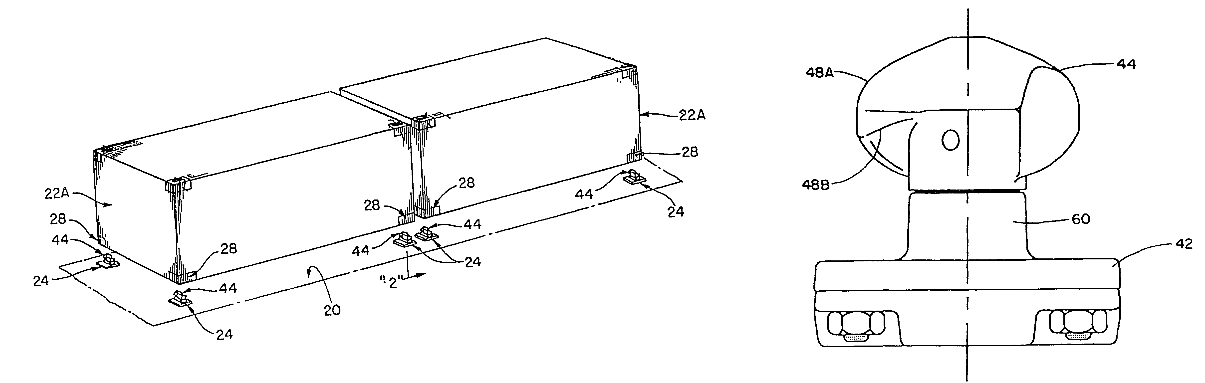
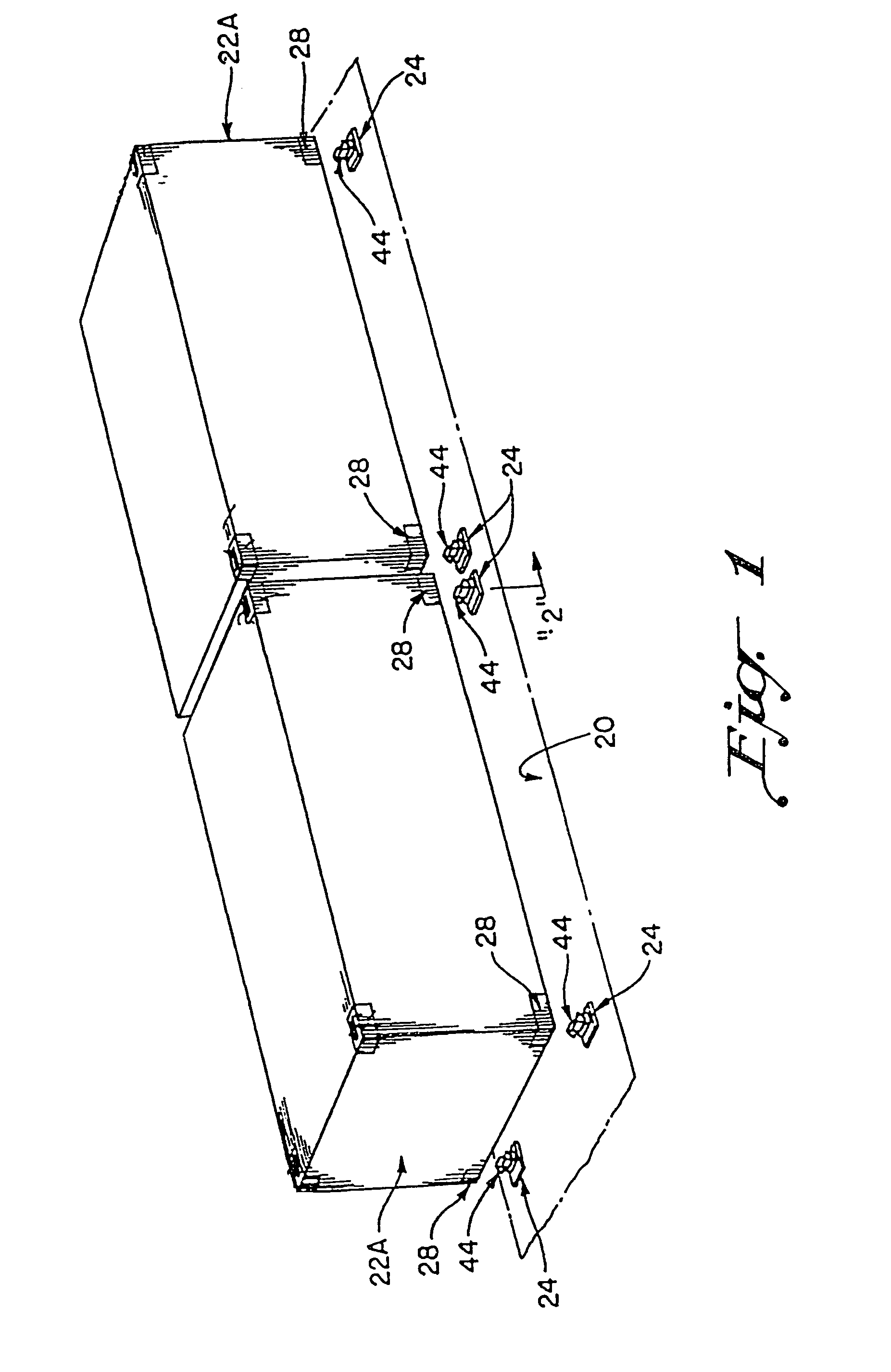
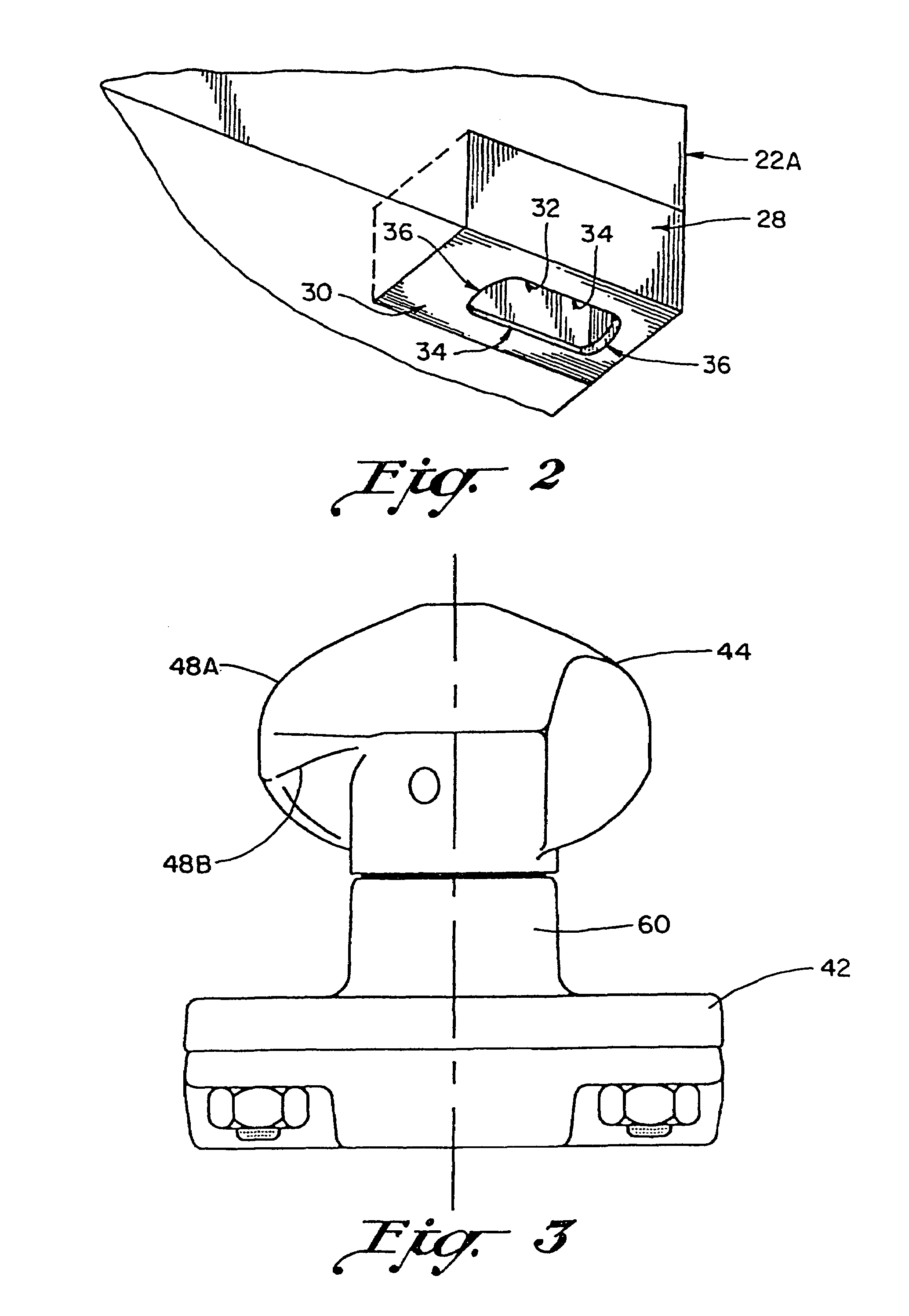
[0032]Referring now to the drawings, the preferred embodiment of the present invention concerns a container securement assembly 24 or system for securing an ISO type container 22 to a support structure 20 such as a carrier deck, which carrier deck is designed to haul ISO type containers through all types of environmental conditions, including often highly variable temperature conditions. Two ISO type containers 22 are illustrated and referenced in juxtaposed, end-to-end relation in superior adjacency to a support structure 20 in FIG. 1. Notably, the International Organization for Standardization (ISO) is an international standard-setting body composed of representatives from national standards bodies. The organization produces world-wide industrial and commercial standards, the so-called ISO standards. A standardized ISO type container (also known as an isotainer) can be loaded on support structures 20 of container ships, railroad cars, and trucks.

[0033]There are five common standa...


PUM


Abstract

A container securement device enables a user to secure a cargo container to a carrier deck. The device includes a base having a projecting shear block received in the lock-actuating opening of the container. A shaft-mounted head rotates between an unlocked or loading position in which the head moves through the locking opening and a locked position in which the container is secured. Automatic entry and release are provided by a selected interchangeable spring element within the base biasing the head to the locked position but permitting movement to the unlocked position when torque is applied by engagement of the container with a cam surface on the head. The spring element may be interchanged as may be required by anticipated climactic and / or temperature conditions. Each spring element is actuable by a uniquely configured shaft member having a spring-receiving end capable of cooperating with at least two types of springs.

Description

BACKGROUND OF THE INVENTION[0001]1. Field of the Invention[0002]The present invention relates to container securement devices and more particularly to improvements in cargo container securement devices providing automatic securement and release of a cargo container.[0003]2. Discussion of Prior Art[0004]Containerized lading has become immensely popular due to advantages such as labor savings resulting from decreased cargo handling. Modular or standardized containers may be shipped from point to point using a variety of different carriers including rail cars, trucks and ships. Such cargo containers are conventionally provided with corner castings including locking openings used in securing the containers to the various types of vehicles upon which they are loaded.[0005]One type of container securement device used in the past is a container pedestal including a base portion upon which a corner of the container rests, as well as vertically extending walls within which a corner of the co...

Claims


Application Information

Patent Timeline
Patent Type & Authority Patents(United States)
IPC IPC(8): B60P7/08
CPCB60P7/132
Inventor BREWSTER, JOHN BASCO
Owner HOLLAND CO
Why Eureka
Try Eureka