Printer

a printing machine and head gap technology, applied in printing, power drive mechanisms, printing mechanisms, etc., can solve the problems of inability to precisely detect the head gap cannot be correctly set, and the distance to the surface of the fabric cannot be precisely detected

Active Publication Date: 2006-08-31
BROTHER KOGYO KK
View PDF4 Cites 32 Cited by
  • Summary
  • Abstract
  • Description
  • Claims
  • Application Information

AI Technical Summary

Benefits of technology

[0010] Aspects of the present invention which has been made in consideration of the above problems are advantageous in that a printer, capable of executing inkjet printing on fabric finely and precisely by correctly detecting the height of the surface of the fabric and constantly keeping the head gap at a proper distance even when there are concavities / convexities on the surface of the fabric and irrespective of the material and color of the fabric, can be provided.

Problems solved by technology

In this configuration, ink mist discharged from the ink heads during printing adheres to the noncontact optical sensor and when a photoreceptor unit or a photoemitter unit is smeared with the ink mist, the distance to the surface of the fabric can not be detected precisely and the head gap can not be set correctly.
Also when the fabric has frayed parts, fuzzy parts, lint, embroidery, etc. thereon, the distance to the surface of the fabric can not be detected precisely and the head gap can not be set correctly.
Further, the head gap can not be set correctly also when reflecting conditions (e.g. reflectance) of light emitted by the photoemitter unit vary depending on the material or color of the fabric.

Method used


Image

  • Printer
  • Printer
  • Printer

Examples


embodiment

[0060] Referring now to the drawings, a description will be given in detail of a preferred embodiment in accordance with the present invention.

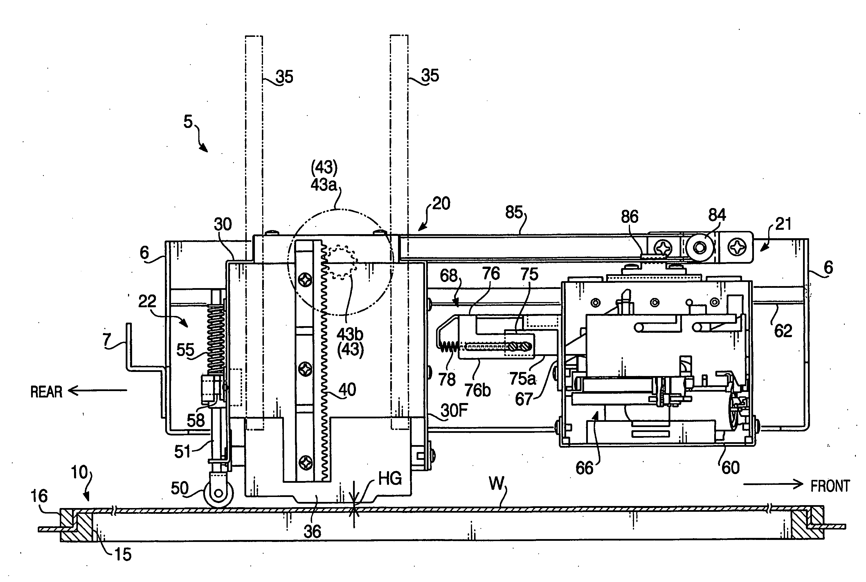
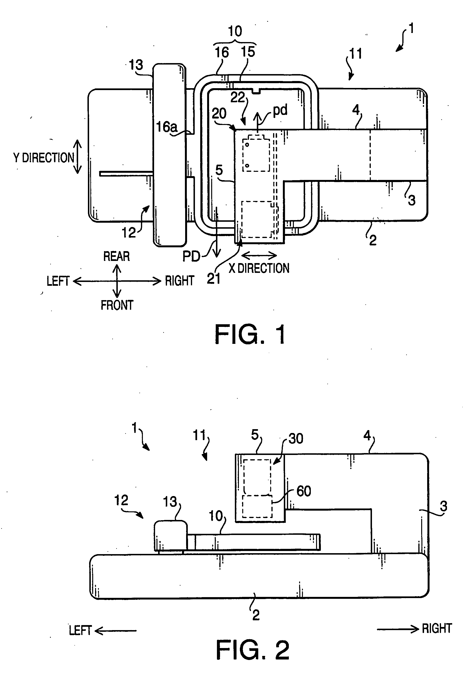
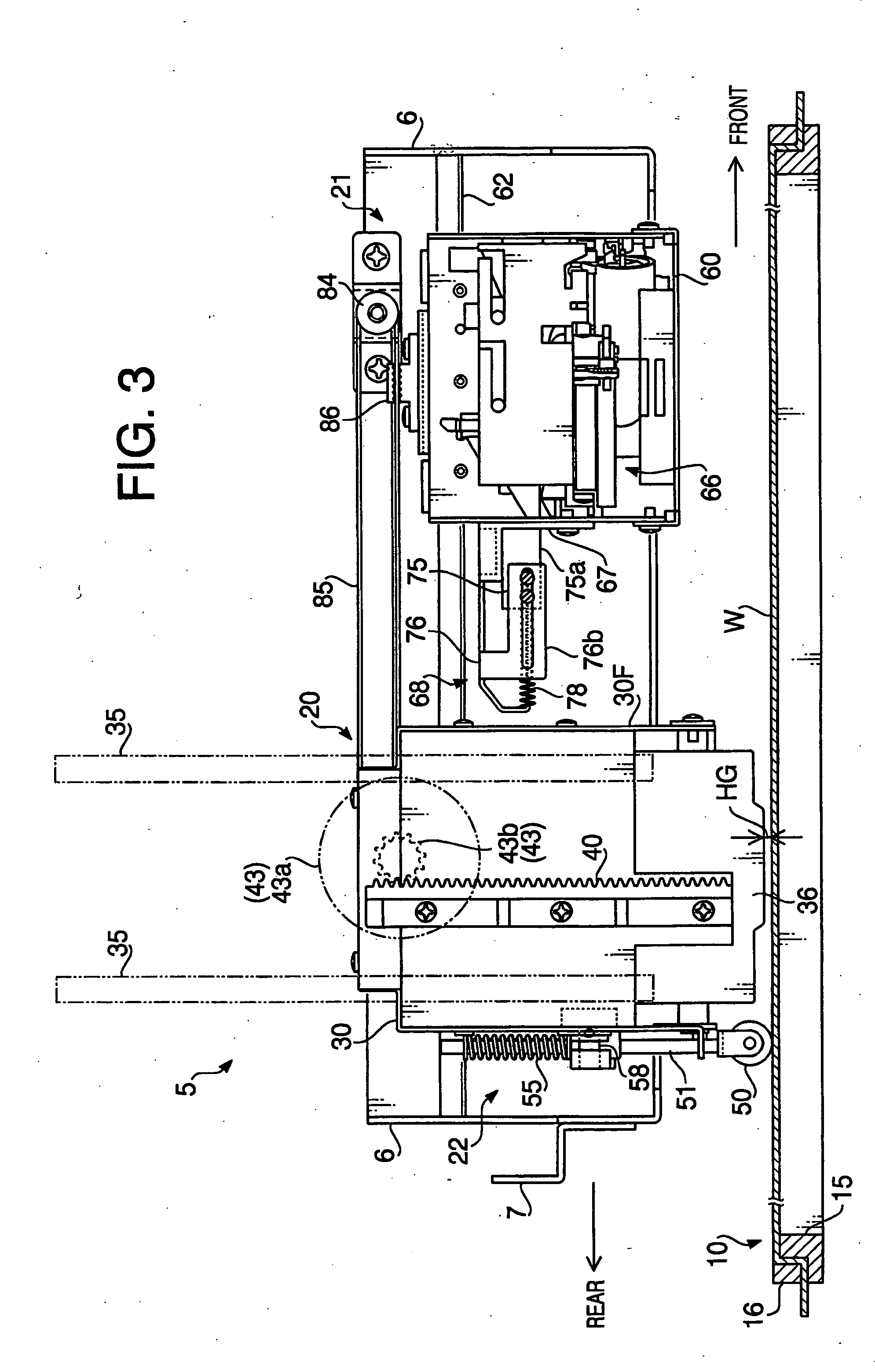
[0061]FIG. 1 is a plan view of a printer 1 in accordance with an embodiment of the present invention. FIG. 2 is a front view of the printer 1. The printer 1 shown in FIGS. 1 and 2 is an inkjet printer for printing a desired pattern, design, etc. on fabric held by a fabric holding frame by discharging color ink from an inkjet head. In the printer 1, an idle roller, rotating freely while making contact with the surface (print surface) of the fabric, is installed in a printing mechanism to be movable in the vertical direction, and the vertical position of the idle roller is detected by a fabric thickness detecting mechanism installed in the printing mechanism.

[0062] As shown in FIGS. 1 and 2, the printer 1 includes a main body 11 and a frame driving mechanism 12. The main body 11 includes a printing mechanism 20, a maintenance mechanism 21 and...


PUM


Abstract

A printer for printing a pattern, design, etc. on fabric comprises a vertical driving unit and a fabric thickness detecting mechanism. The vertical driving unit moves a printing unit including a print head in the vertical direction to let the print head move toward and away from the fabric held by a fabric holding frame. The fabric thickness detecting mechanism includes an idle roller which is attached to the printing unit to be on the preceding side of the printing unit in the printing direction of the print head to rotate freely while contacting the print surface of the fabric. The fabric thickness detecting mechanism detects the height of the print surface of the fabric based on the position of the idle roller. The vertical driving unit is controlled to drive the printing unit vertically according to the height of the print surface detected by the fabric thickness detecting mechanism.

Description

CROSS-REFERENCE TO RELATED APPLICATION [0001] This application is related to Japanese Patent Application No. 2005-054248, both filed on Feb. 28, 2005, the entire subject matter of which is incorporated herein by reference. BACKGROUND [0002] 1. Technical Field [0003] Aspects of the present invention relate to a printer for executing inkjet printing on fabric held by a fabric holding frame. [0004] 2. Description of Related Art [0005] A variety of printing techniques have been proposed for printing desired patterns, designs, etc. on various types of fabrics, and a variety of inkjet printing devices, capable of printing desired patterns, designs, etc. on the surface of fabric by moving the fabric or a print head relative to each other in an X direction and a Y direction (orthogonal to the X direction) while letting ink nozzles discharge color ink onto the fabric according to print data, have been proposed. [0006] For example, in a printer described in Japanese Patent Provisional Publica...

Claims


Application Information

Patent Timeline
Patent Type & Authority Applications(United States)
IPC IPC(8): B41J25/308
CPCB41J25/308
Inventor KUKI, MASAKAZUKAWAGUCHI, YASUHIKOKAWABE, NORIKO
Owner BROTHER KOGYO KK
Why Eureka
Try Eureka