
Method of demosaicing a digital mosaiced image

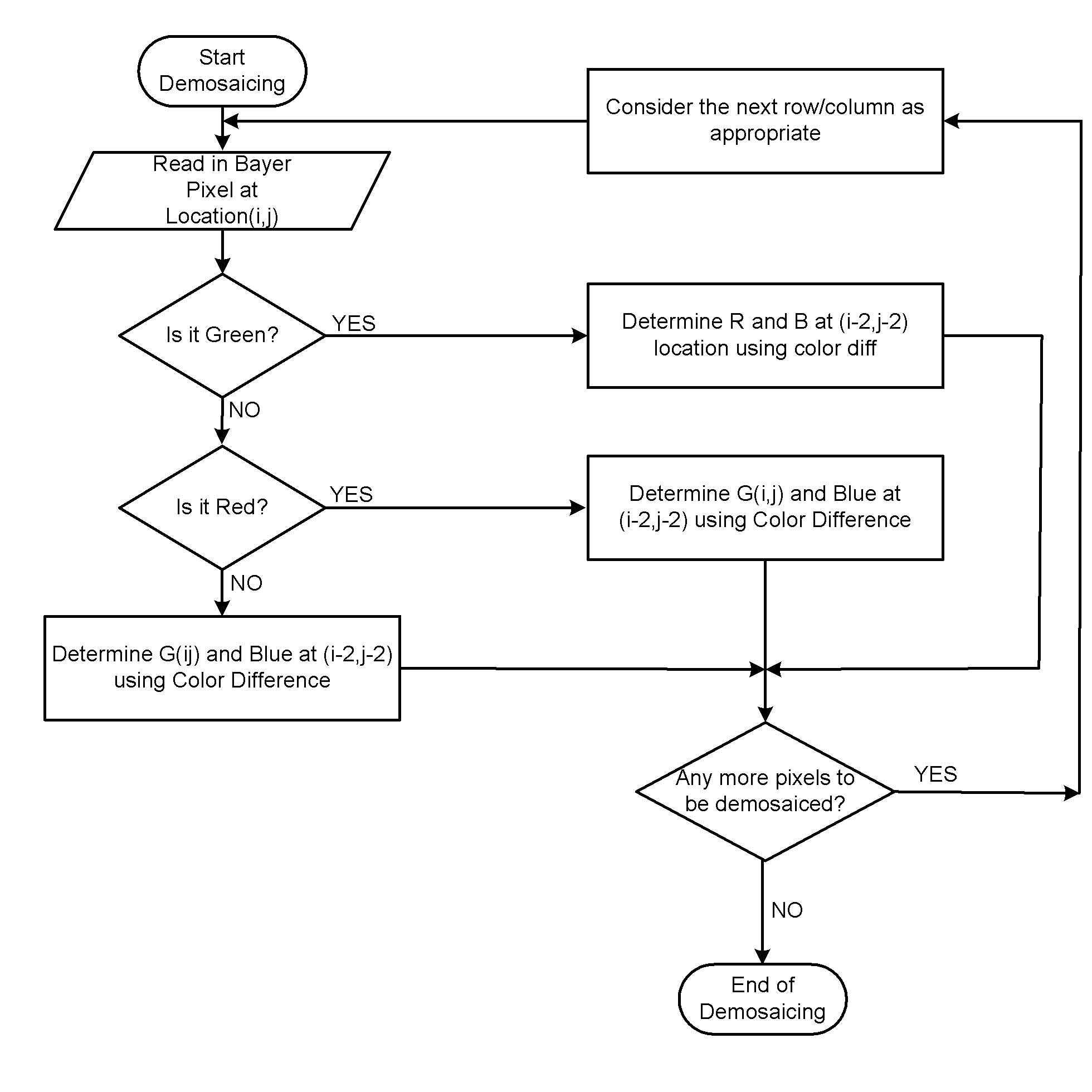
a demosaicing and mosaiced image technology, applied in the field of digital image processing, can solve the problems of poor quality of demosaicing images obtained from conventional techniques that are suitable for embedded applications, difficult to manage from a memory complexity point, and unsuitable for embedded applications

Inactive Publication Date: 2008-10-16
ARICENT INC
View PDF2 Cites 76 Cited by
  • Summary
  • Abstract
  • Description
  • Claims
  • Application Information

AI Technical Summary

Problems solved by technology

However, such methods may require an initialization.
Further, the quality of demosaiced images obtained from conventional techniques that are suitable for embedded applications are not as good as that obtained from the iterative or highly complex algorithms, and therefore, there clearly is a need for techniques that provide the quality / performance of the highly complex algorithms but at a much lower complexity thereby making them suitable for embedded applications.
Hence, another difficulty with state-of-the-art algorithms is the complexity, several conventional algorithms are iterative and thus are not suited for, but is not limited to, embedded applications.
Several other techniques utilize the whole image for computations and this is very difficult to manage from a memory complexity point of view.
Furthermore, most of the aforementioned arts provide complex algorithms that impart a slightly soft look to the image, i.e., images are slightly blurred with some loss in very high detail regions of the image.
Also, detail that is lost can never be perfectly regained.
Thus, zipper artifact and false color artifacts are present even in the best of algorithms.
As a result, scenes containing very high detail such as, but is not limited to, beads in the lady image, fence in the lighthouse are prone to artifacts when demosaiced.

Method used


Image

  • Method of demosaicing a digital mosaiced image
  • Method of demosaicing a digital mosaiced image
  • Method of demosaicing a digital mosaiced image

Examples


example 1

[0052]An example to illustrate gradient constancy is provided hereinbelow:

[0053]In an image neighborhood, even if for a single pixel the computed gradient is not same as the actual gradient then it will result in artifacts in the demosaiced image. To prevent this the following gradient constancy enforcement method is employed.

[0054]FIG. 3 (a) is an example Bayer Array, where R13 is the pixel that is being processed, then the gradient is calculated for the R25 pixel, which is the current pixel. So ΔH and ΔV for R25 is obtained and the following decision can be done, ΔH is the horizontal gradient of R25 and ΔV is the vertical gradient of R25[0055]If ΔH[0056]Gradient (i,j)=1[0057]Else[0058]Gradient (i,j)=−1.[0059](i,j) are the coordinates of the R25 pixel location.

In this example, since the final value of Green pixel G13 is to be obtained at R13 location, a 5×5 window is taken around R13, which is depicted in FIG. 3(a).

[0060]Further, in this example, gradient is a table that stores the...

example 2

[0071]An example equation illustrating the method in accordance with an embodiment is disclosed hereinbelow. FIG. 5 illustrates an example 7×7 Bayer area. In this example, to determine green G13 at red pixel R13, the color difference R-G at the center pixel in the horizontal direction is determined as,

R13−G13=α*(R11−G11)+β*(R12−G12)+γ*(R14−G14)+δ*(R15−G15)

i.e., the color difference at the center pixel is determined as the weighted average of the color difference of the neighboring pixels in the example horizontal orientation. The weights in this example add up to unity (α+β+γ+δ=1).

In the present implementation weights are chosen to be one of the following two sets (with no loss of generality)

α=¼, =¼, γ=¼, δ=¼

α=⅛, β=⅜, γ=⅜, δ=⅛. It is to be appreciated that the weights in computing constant color difference formula can vary from the ones disclosed herein and can be adaptive.

[0072]In the above expression, all the colors are not known. R11, G12, R13, G14 and R15 are known. Since the pi...

example 3

[0074]An example illustrating the method in accordance with the above embodiment of the invention is disclosed hereinbelow: In this example method a weighted average of the horizontal and the vertical interpolated or demosaiced values are taken with weights governed by the value of the gradient

[0075]The sum of the gradient values are computed. The gradient values can be obtained as indicated in example 2 disclosed hereinabove for computing G13.

S13=ΔH+ΔV.

Horizontal and vertical gradients are divided with the sum to get the normalised example horizontal and vertical gradients.

NΔH=ΔH / S13

NΔV=ΔV / S13

This process makes NΔH+NΔV=1, so that they can be used as weights. The final green value, in this example is thus obtained using a combination of the horizontal and vertical estimates with the normalized values obtained used as weights as given hereinbelow:

G13=NΔH*G13V+NΔV*G13H.

For instance: if ΔH=1.7 and ΔV=3, then S13=4.7 and finally NΔH=0.361 and NΔV=0.639. Also NΔH+NΔV=1.

The inverse grad...


PUM


Abstract

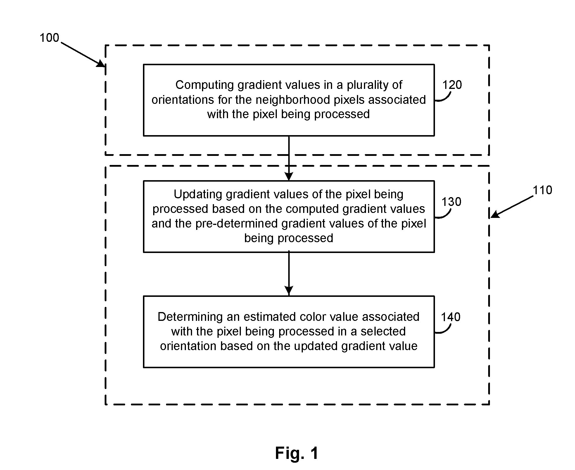
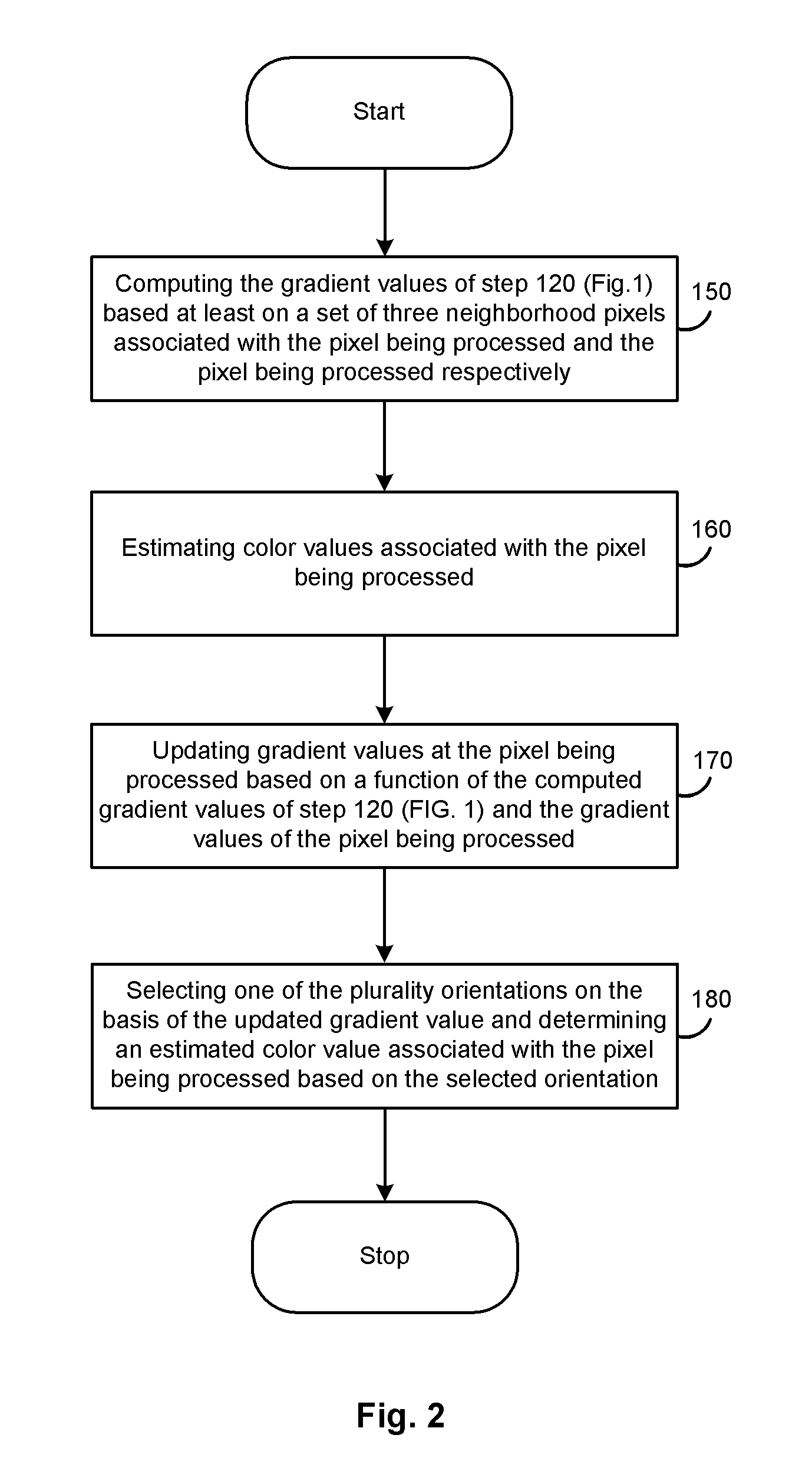
In one example embodiment, a method enables, computing, for a first pixel in the digital mosaiced image, the first pixel being characterized by a first color component and a first set of gradient values in a plurality of orientations, gradient values in the plurality of orientations for a second pixel in the neighborhood of the first pixel. Color values in the plurality of orientations corresponding to a second color component associated with the first pixel based on the set of first gradient values are estimated. The first set of gradient values based at least in part on the computed gradient values is updated. One of the plurality of orientations of the estimated color value based on the updated set of first gradient values is selected and one of the estimated color values corresponding to the selected orientation is determined.

Description

FIELD OF THE INVENTION[0001]The present invention relates to the field of digital image processing. In particular the present invention provides an enhanced method of demosaicing a digital mosaiced image.BACKGROUND OF THE INVENTION[0002]Imaging pipeline refers to the processing that a captured image undergoes before it can be viewed or compressed. Most conventional cameras use single color sensors, i.e., the sensors are sensitive only to the luminance. Color filter arrays (CFAs) are used on top of the sensors to sample one color at each pixel, for example, the Bayer color filter array samples three colors—red, blue and green all over the sensor, sampling green at twice the rate of red and blue. Each pixel therefore has information of only one color. Color filter array interpolation or demosaicing refers to the process of computing all the missing colors at all the pixels. Demosaicing is one of the most complex stages of the imaging pipeline and a good demosaicing algorithm is very i...

Claims


Application Information

Patent Timeline
IPC IPC(8): G06K9/00
CPCG06T3/4015H04N9/045H04N2209/046H04N23/843H04N25/134
Inventor GUPTA, PALLAPOTHU SHYAM, SUNDERA, BALA, KOTESWARAGOVINDARAO, KRISHNA ANNASAGARSUMAN, KOPPARAPUMEKA, RAMAKRISHNA VENKATAKORADA, RAMKISHOR
Owner ARICENT INC
Learn More