Supercharge Your Innovation With Domain-Expert AI Agents!

Image forming apparatus

a technology of forming apparatus and forming plate, which is applied in the direction of electrographic process apparatus, instruments, optics, etc., can solve the problems of increasing costs, unable to completely restrain offset with respect to a specified type of sheet, and difficulty in one single bias power supply to set an optimum bias to multifarious types of sheets and a variety of environments, so as to reduce the offset of unfixed toner. , the effect of low cos

Inactive Publication Date: 2008-10-16
CANON KK
View PDF4 Cites 13 Cited by
  • Summary
  • Abstract
  • Description
  • Claims
  • Application Information

AI Technical Summary

Benefits of technology

[0014]It is an object of the present invention, which was devised in view of the problems described above, to provide an image forming apparatus capable of restraining the offset of an unfixed toner at low costs.
[0015]It is another object to provide an image forming apparatus including a toner offset restraining mechanism at low costs, which has flexibility to multifarious types of sheets and a variety of environments.

Problems solved by technology

As a result, according to the configuration shown in Japanese Patent No. 3053459, it is difficult for one single bias power supply to set an optimum bias to the multifarious types of sheets and a variety of environments.
Therefore, this has proven that there is a case in which the offset can not be completely restrained with respect to a specified type of sheet.
The system shown in Japanese Patent Application Laid-Open No. 2000-338807 solves the problem given above but needs to have two power supplies, which leads to a rise in costs.
In terms of a trend toward lower prices over the recent years, a cost reduction is an indispensable issue, and the user's requests can not be satisfied by any technologies having none of high performance at low costs.
This method, however, has also proven that there is the case in which the offset can not be completely restrained with respect to the specified type of sheet as in the case of Japanese Patent No. 3053459.
S64-065589, it is difficult to set the optimum surface potential to the multifarious types of sheets and the variety of environments, and it has been recognized that there is the case in which the offset can not be completely restrained with respect to the specified type of sheet.

Method used


Image

  • Image forming apparatus
  • Image forming apparatus
  • Image forming apparatus

Examples


first embodiment

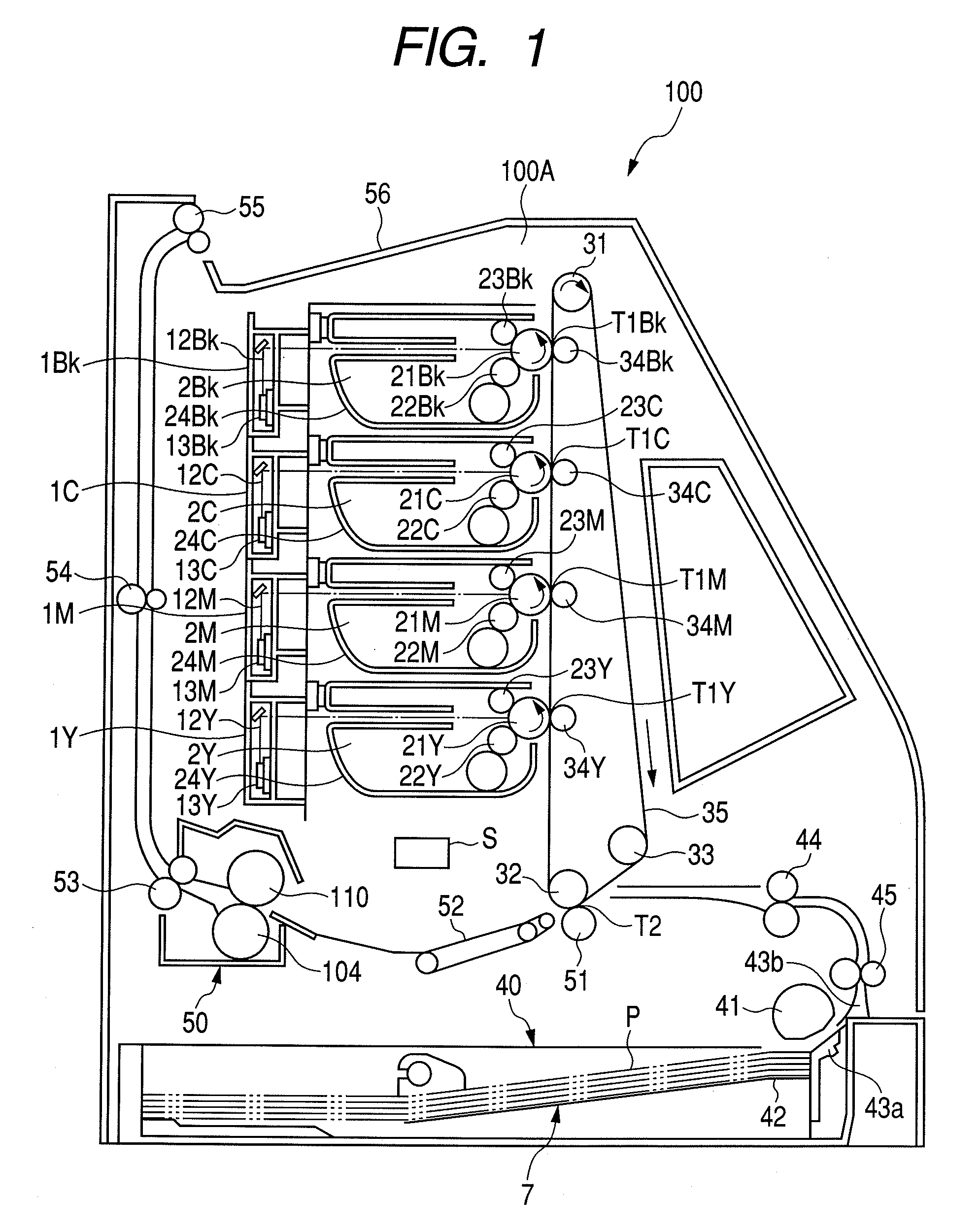
[0033]FIG. 1 is a view illustrating an outline configuration of a color image forming apparatus by way of one embodiment of the image forming apparatus according to the present invention. A color image forming apparatus 100 in the first embodiment is classified as a laser printer, however, the present invention is not limited to such a laser printer.

[0034]At first, the whole configuration of the image forming apparatus in the first embodiment will be outlined.

[0035]A color laser printer 100 defined as the image forming apparatus in the first embodiment includes four image forming units that form images assuming colors such as Y (yellow), M (magenta), C (cyan) and Bk (black). The image forming units are based on a system of process cartridges 2 (2Y, 2M, 2C and 2Bk). The process cartridges 2 (2Y, 2M, 2C and 2Bk) are detachably attached to an image forming apparatus body 100A.

[0036]The process cartridges 2 (2Y, 2M, 2C and 2Bk) have drum-shaped electrophotographic photosensitive members...

second embodiment

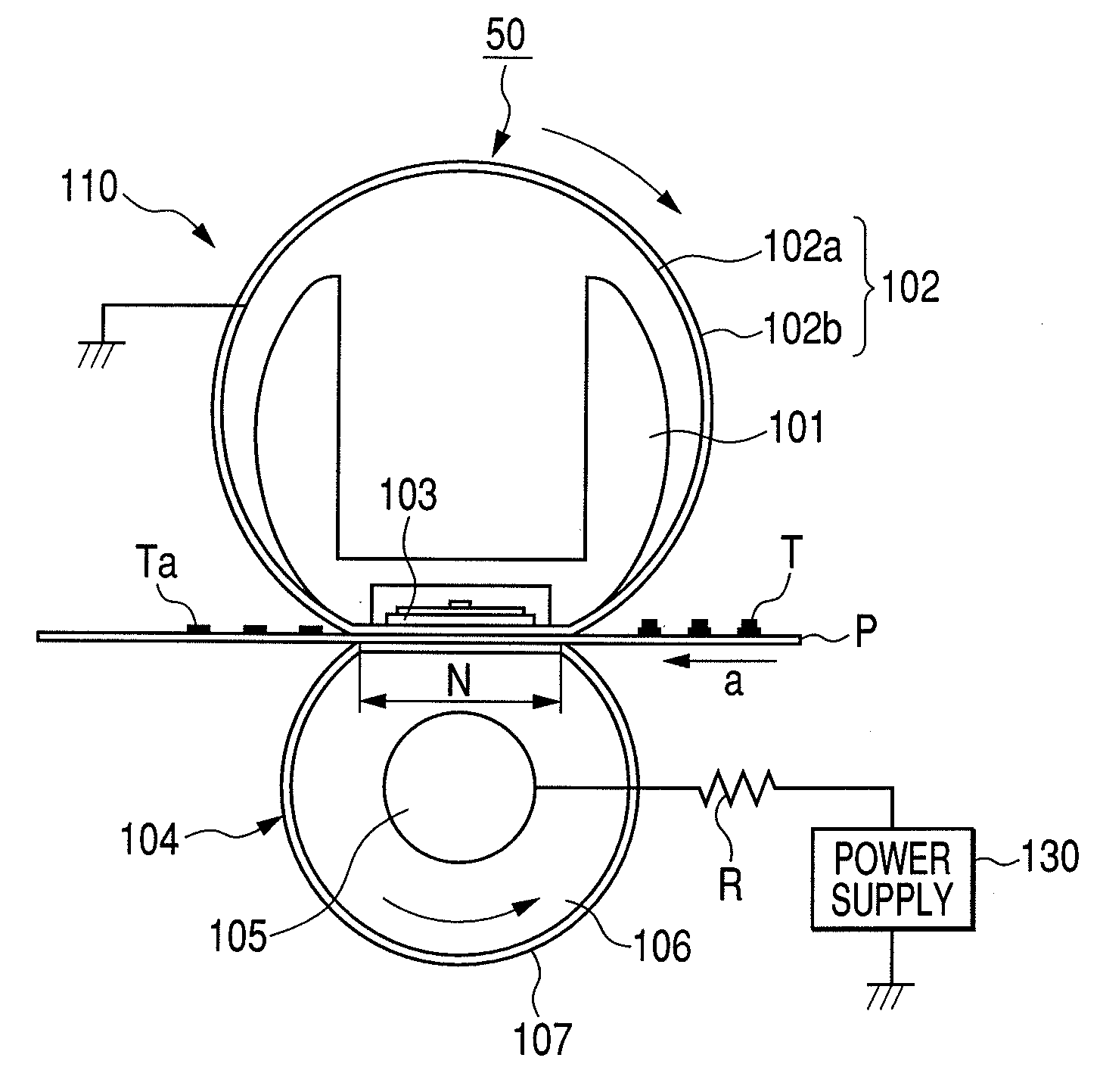
[0080]Next, a second embodiment of the present invention will be described. The basic configurations of the image forming apparatus 100 and the fixing apparatus 50 according to the second embodiment are the same as those in the first embodiment discussed with reference to FIGS. 1 and 2. Accordingly, the descriptions of the image forming apparatus 100 and the fixing apparatus 50 involve quoting the descriptions in the first embodiment, and the discussion herein will be focused on constructive portions characteristic of the second embodiment.

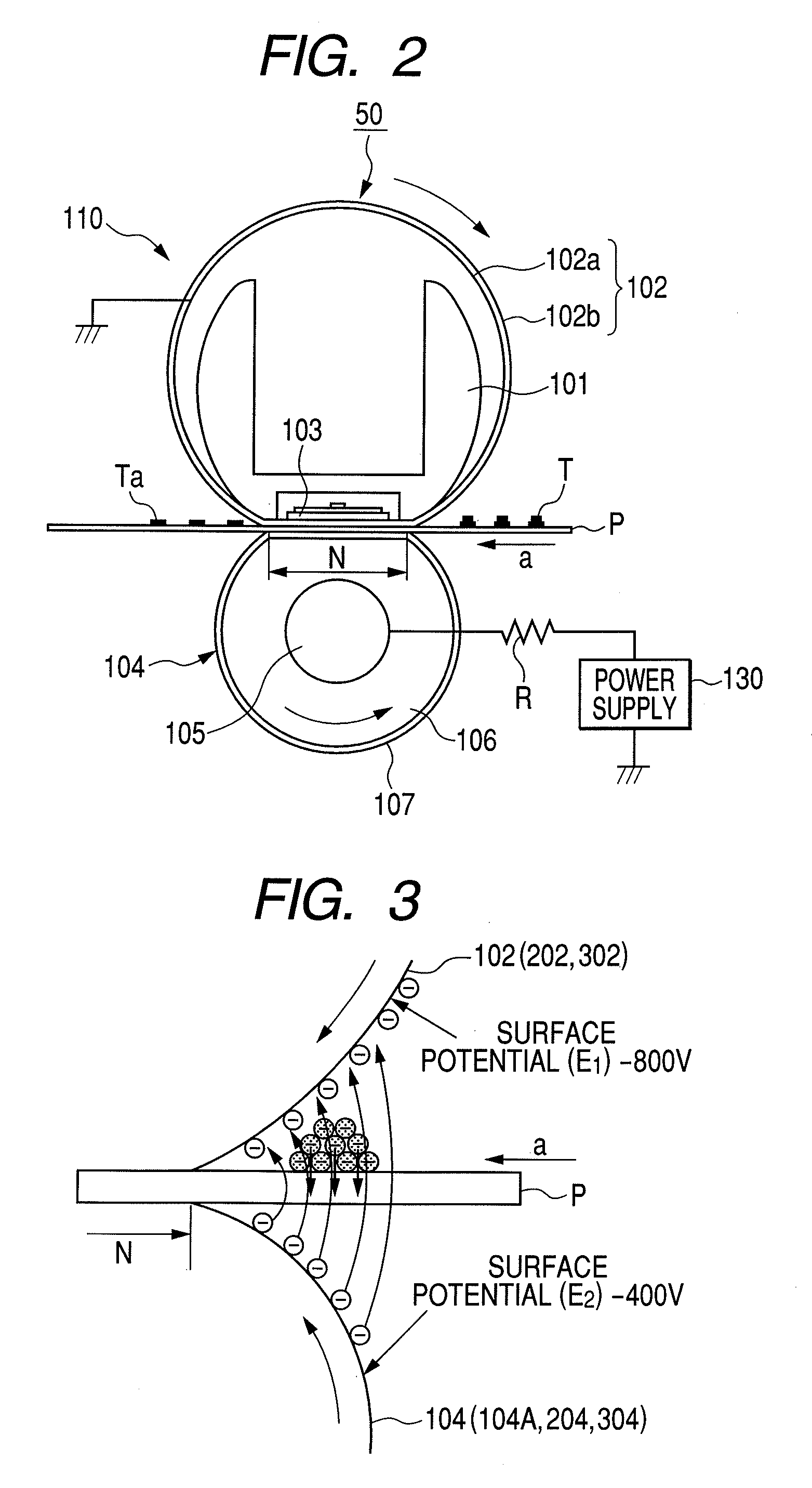
[0081]In the case of performing the control exemplified in the first embodiment, there occurs a phenomenon that the absolute value of the surface potential of the metal sleeve 102 decreases stepwise due to the potential of the recording material P, the environment and the toner charging quantity during the conveyance of the recording material P.

[0082]For example, as to the surface potential E1 of the metal sleeve 102, the surface potential of minu...

third embodiment

[0087]Next, a third embodiment of the present invention will be discussed. The basic configurations of the image forming apparatus 100 and the fixing apparatus 50 according to the third embodiment are the same as those in the first embodiment discussed with reference to FIGS. 1 and 2. Accordingly, the descriptions of the image forming apparatus 100 and the fixing apparatus 50 involve quoting the descriptions in the first embodiment, and the discussion herein will be focused on constructive portions characteristic of the third embodiment.

[0088]The case of performing the control described in the first and second embodiments has proven that the offset occurs if the environment for installing the apparatus is changed.

[0089]The third embodiment will exemplify an example in which a sensor (hereinafter referred to as “environment sensor”) S (see FIG. 1) for detecting a temperature and humidity in the basic configuration of the image forming apparatus described in the first embodiment, and ...


PUM


Abstract

The image forming apparatus includes a fixing apparatus capable of restraining offset of a toner in multifarious types of sheets and in a variety of environments at low costs. The fixing apparatus has a rotary fixing member and a nip forming member which forms a fixing nip portion by coming into contact with the rotary member. A recording material bearing an unfixed toner image is conveyed while being pinched by the nip portion. The fixing apparatus fixes a toner image onto the recording material. The fixing apparatus further has a bias applying means which applies a bias to the nip forming member. The bias applying means, before the recording material reaches the nip portion, applies a first bias to the nip forming member so that a surface of a rotary member is charged with electricity, and applies a second bias to the nip forming member while the recording material is conveyed by the nip portion.

Description

BACKGROUND OF THE INVENTION[0001]1. Field of the Invention[0002]The present invention relates to an image forming apparatus such as a copying machine and a printer.[0003]2. Description of the Related Art[0004]In the image forming apparatus such as the printer, the copying machine and a facsimile that have hitherto employed an electrophotographic technology, a fixing apparatus 50 having a configuration illustrated in FIG. 14 has been widely adopted as means of fixing an unfixed toner image formed and borne on a recording material. The fixing apparatus 50 includes a heating unit 110 coming into contact with an unfixed toner image. The heating unit 110 has a rotary fixing member (hereinafter simply referred to as “sleeve”) 102 such as an endless belt and a roller. The fixing apparatus 50 has a pressure roller 104 defined as a nip forming rotary member. A recording material P is conveyed and pinched by a fixing nip portion N formed between the sleeve 102 and the pressure roller 104, and...

Claims


Application Information

Patent Timeline
Patent Type & Authority Applications(United States)
IPC IPC(8): G03G15/20
CPCG03G15/2039G03G2215/2038
Inventor SUZUKI, YOUHEIYAMAMOTO, TETSUYAUCHIDA, MICHIOSHIDA, TOMONORIMITSUHASHI, KEISUKE
Owner CANON KK
Features
  • R&D
  • Intellectual Property
  • Life Sciences
  • Materials
  • Tech Scout
  • Unparalleled Data Quality
  • Higher Quality Content
  • 60% Fewer Hallucinations
Learn More