Progressive Gearing

Active Publication Date: 2008-10-23
BLESS WERNER M
View PDF11 Cites 9 Cited by
  • Summary
  • Abstract
  • Description
  • Claims
  • Application Information

AI Technical Summary

Benefits of technology

[0019]Preferably the radius of curvature of the curve locating the teeth is a minimum where the spur gear comes into contact or meshes with the toothed structure when the steering gear is in its center position. This results in the translation ratio changing relatively slowly with small excursions from the center position, it results in avoiding

Problems solved by technology

However, these gear assemblies are structured relatively complicated and are thus correspondingly expensive in manufacture and maintenance.
It is also a drawba

Method used


Image

  • Progressive Gearing
  • Progressive Gearing
  • Progressive Gearing

Examples


Example

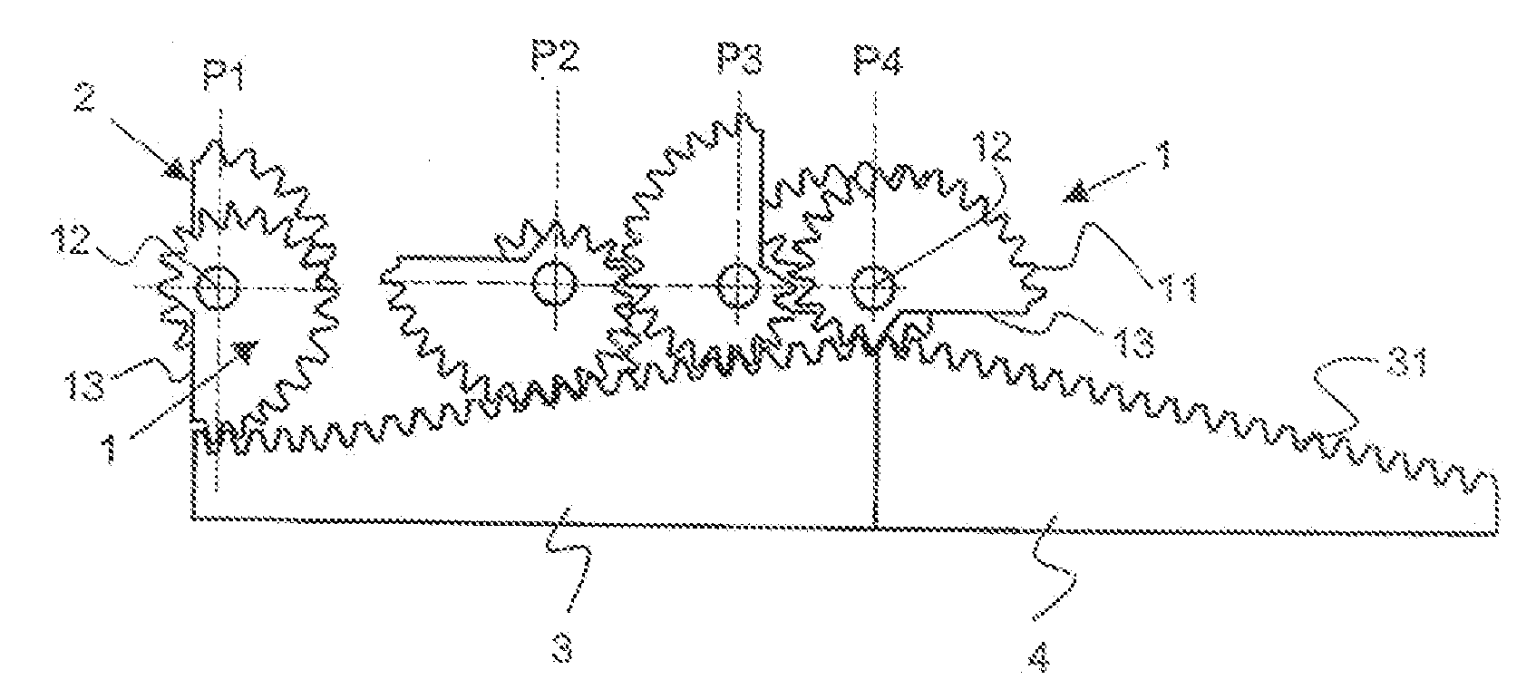
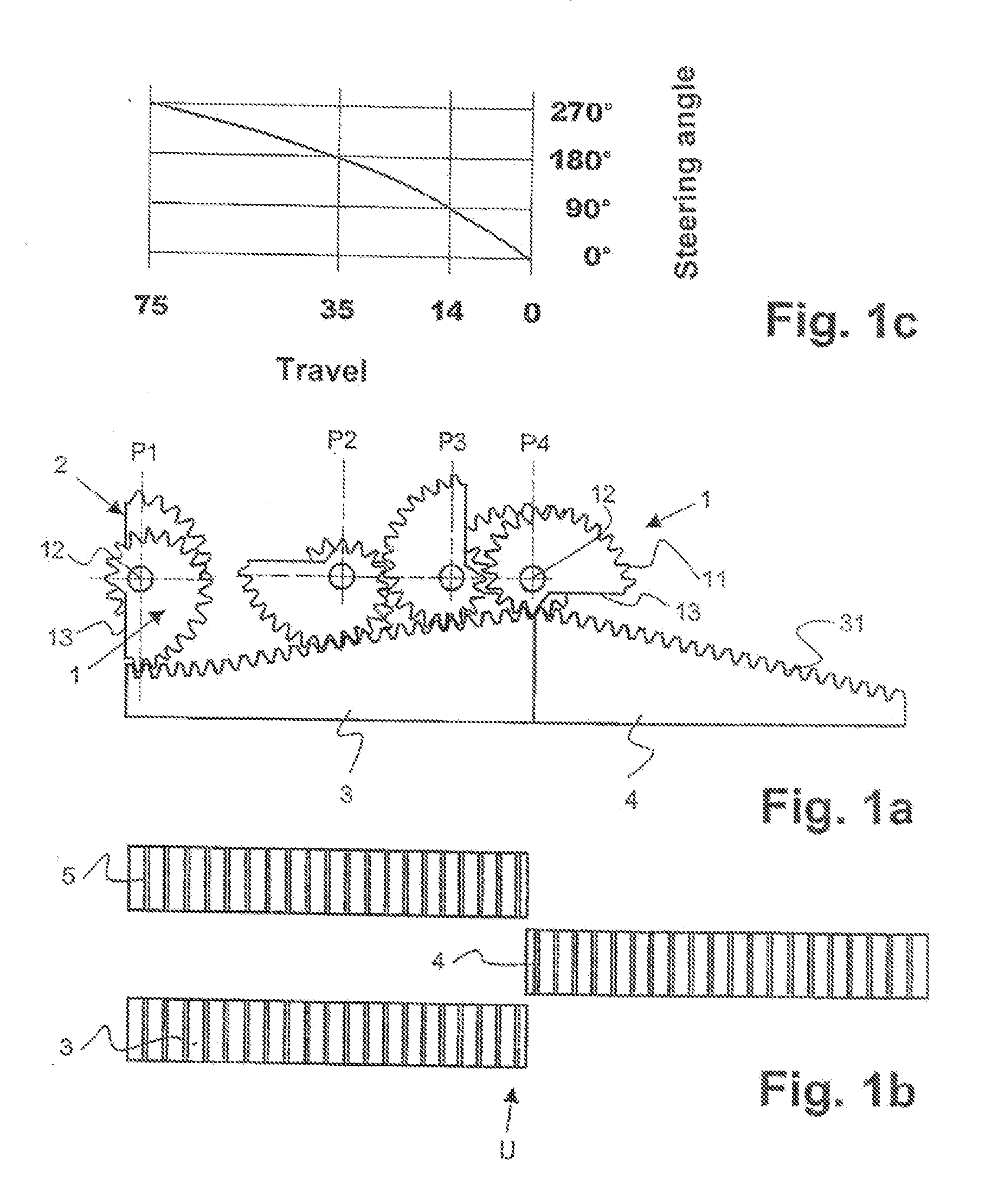
[0048]Referring now to FIGS. 1a and 1b there is illustrated a first example embodiment of the progressive gear assembly in accordance with the invention as employed, for instance, in a motor vehicle. The gear assembly comprises at least two, preferably three spur gears 1, 2 rotatable about a common axis of rotation 12. For this purpose the spur gears 1, 2 are connected to a steering shaft (not shown). The steering shaft is turned to the desired rotational position in each case by means of a steering wheel of the vehicle.

[0049]Each of the spur gears 1, 2 meshes with a toothed structure in the form of a gear rack 3, 4, 5 while being rolled along the gear racks 3, 4, 5. This results in either the axis of rotation 12 being shifted along a preferably horizontal straight line or the gear racks 3, 4, 5 being shifted correspondingly in their longitudinal direction. The third gear rack 5 provided merely optionally is depicted lighter than the first and second gear racks 3, 4 in FIG. 1b.

[005...


PUM


Abstract

A progressive gear assembly comprises at least one spur gear (1, 2) and a toothed structure (3, 4, 5, 7, 8) with which the spur gear (1, 2) meshes. The spur gear (1, 2) has teeth (11) arranged along a curve (10), the curve (10) comprising a radius of curvature (r) which monotonically rises over an angular range of more than 90° of the curve (10). Preferably the curve is a spiral, particularly a logarithmic spiral. This gear assembly is configured compact and simple, features smooth running and achieves a late end point.

Description

FIELD OF THE INVENTION[0001]The invention relates to a progressive gear assembly as set forth in the preamble of claim 1.BACKGROUND OF THE INVENTION[0002]Progressive gear assemblies find application, for example, in vehicle steering systems, particularly for motor vehicles. It is usually the case that turning the steering wheel is communicated via a steering shaft to a gear wheel meshing with a gear rack. When driven in this way the gear wheel shifts the gear rack which positions the wheels accordingly. With a progressive steering or progressive gear assembly the translation ratio is reduced from a maximum value in a center range of the steering wheel when the steering wheel is turned. This means that in the straight-ahead position of the steering wheel a relatively large turn of the steering wheel produces a small change in direction of the driving track, whereas when maneuvering with the steering wheel already strongly turned, just a relatively small change in turn produces a larg...

Claims


Application Information

Patent Timeline
IPC IPC(8): B62D3/02
CPCB62D3/12F16H19/04F16H35/02Y10T74/19884Y10T74/1967Y10T74/19679F16H2035/003
Inventor BLESS, WERNER M.ROTT, ERWIN
Owner BLESS WERNER M
Why Eureka
Try Eureka