Blowby gas returning device
a technology of blowby gas and return device, which is applied in the direction of combustion engine, charge feed system, non-fuel substance addition to fuel, etc., can solve the problems of significant affecting the air-fuel ratio, the control of the air-fuel ratio of the engine, and the change of the rotational speed of the engine, so as to prevent the fluctuation of the air-fuel ratio
- Summary
- Abstract
- Description
- Claims
- Application Information
AI Technical Summary
Benefits of technology
Problems solved by technology
Method used
Image

Examples
first embodiment
[0018]A detailed description of a first preferred embodiment of an engine system embodying a blowby gas returning device of the present invention will now be given referring to the accompanying drawings.
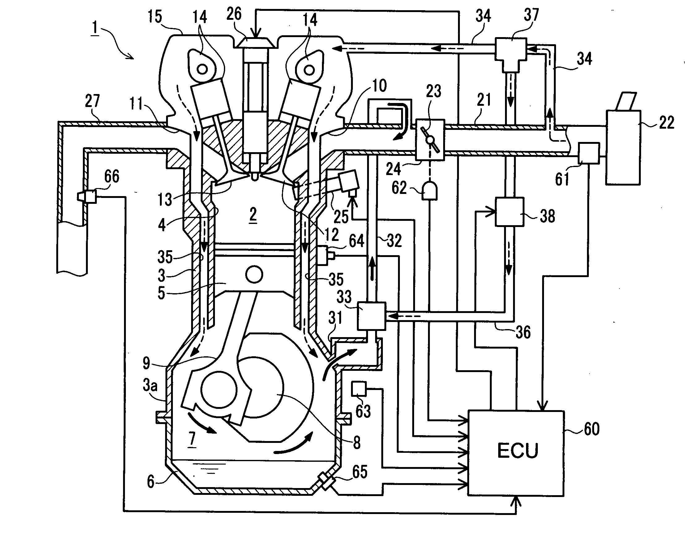
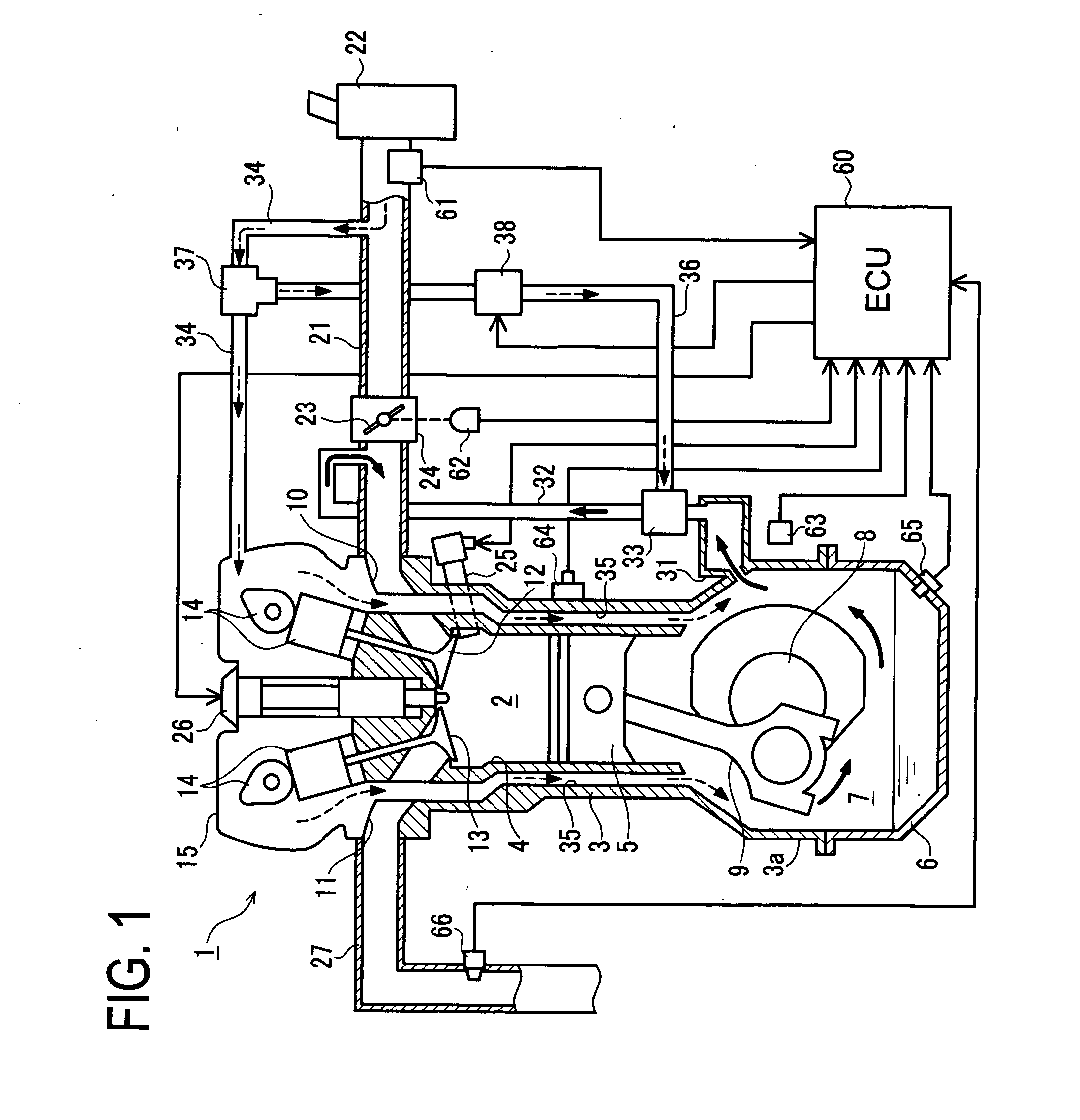
[0019]FIG. 1 is a schematic configuration view of the engine system including the blowby gas returning device of the present embodiment. An engine 1 constituting this engine system is a direct-injection multicylinder spark-ignition engine arranged to directly inject fuel into a combustion chamber 2. An engine block 3 of this engine 1 is formed with a plurality of cylinder bores 4 in each of which a piston 5 is placed to be movable up and down. The engine block 3 includes a crank case 3a as a lower part of the engine block 3, and an oil pan 6 combined with the crank case 3a. Those crank case 3a and oil pan 6 form a crank chamber 7. In the crank chamber 7, a crank shaft 8 is rotatably supported, to which each of the piston 5 is connected through a connecting rod 9.
[0020]The combustion ...
second embodiment
[0040]Next, a second embodiment embodying an engine system embodying a blowby gas returning device of the present invention will now be given referring to the accompanying drawings.
[0041]In the second and subsequent embodiments explained below, identical components or parts to those in the first embodiment are given the same reference signs as in the first embodiment. The following explanation is made with a focus on differences from the first embodiment.
[0042]The second embodiment differs from the first embodiment in the details of the blowby gas returning control to be executed by the ECU 60. FIG. 5 is a flowchart showing the details of the blowby gas returning control. The ECU 60 executes this control after the start of the engine 1.
[0043]Specifically, at step 200, the ECU 60 reads the air-fuel ratio calculated from the oxygen concentration Ox detected by the oxygen sensor 66. The ECU 60 determines at step 210 whether or not the read air-fuel ratio is shifting to rich side. This ...
third embodiment
[0046]Next, a third embodiment of an engine system embodying a blowby gas returning device of the present invention will now be given referring to the accompanying drawings.
[0047]The third embodiment differs from the first and second embodiments in the details of the blowby gas returning control to be executed by the 60. FIG. 6 is a flowchart showing the details of the blowby gas returning control. The ECU 60 executes this control after the start of the engine 1.
[0048]Specifically, at step 300, the ECU 60 reads the oil temperature THO detected by the oil temperature sensor 65. The ECU 60 determines at step 310 whether or not the read oil temperature THO is higher than a predetermined value T1 (e.g. “−40° C.”). This determination is made to check that the blowby gas mixed in the lubricant in the oil pan 6 begins to vaporize when the oil temperature THO exceeds the predetermined value T1, leading to an increase in fuel constituent concentration of the blowby gas in the crank chamber 7...
PUM
 Abstract
Description
Claims
Application Information
 - R&D Engineer
- R&D Manager
- IP Professional
- Industry Leading Data Capabilities
- Powerful AI technology
- Patent DNA Extraction
Browse by: Latest US Patents, China's latest patents, Technical Efficacy Thesaurus, Application Domain, Technology Topic.
© 2024 PatSnap. All rights reserved.Legal|Privacy policy|Modern Slavery Act Transparency Statement|Sitemap