Radiation imaging system

a technology of imaging system and radiography, applied in the field of radiographic image capturing system, can solve the problems of not being able to generate accurate corrective images, not being able to apply the disclosed method to the image capturing process for capturing successive images, and not being able to achieve accurate corrective images, etc., to achieve the effect of reducing the cost, preventing the s/n ratio and contrast from being lowered, and lowering the degree of freedom

Active Publication Date: 2016-04-26
FUJIFILM CORP
View PDF20 Cites 2 Cited by
  • Summary
  • Abstract
  • Description
  • Claims
  • Application Information

AI Technical Summary

Benefits of technology

[0016]The present invention has been made in view of the aforementioned drawbacks. It is an object of the present invention to provide a radiographic image capturing system, which is simple in structure and capable of capturing radiographic images while staying clear of areas where afterimage phenomena (bright-burn or ghost phenomena) tend to occur, thereby preventing the S / N ratio and contrast from being lowered, and which is reduced in cost without lowering the degree of freedom in designing the radiation detecting device.
[0037]The radiographic image capturing system according to the present invention predicts a timing at which an afterimage phenomenon (a bright-burn or a ghost phenomenon) will occur prior to a radiographic image capturing process, and moves at least the converter at the predicted timing. Therefore, it is possible to capture an image while avoiding a region in which afterimage phenomena tend to occur. In other words, with a simple arrangement and independently of the outer profile of the subject, it is possible to capture an image while avoiding a region where afterimage phenomena may occur. The radiographic image capturing system further is capable of preventing the S / N ratio and contrast from being lowered, and the cost thereof can be reduced without lowering the degree of freedom in designing the radiation detecting device. According to the present invention, furthermore, the radiographic image capturing system can easily be applied to a tomosynthetic image capturing process, for example, for capturing ten to several tens of radiographic images within a short period of time, thereby enabling an increase in the image quality of a reconstructed tomographic image of the subject.

Problems solved by technology

The method disclosed in Japanese Laid-Open Patent Publication No. 2003-107163 is problematic in that, since the scintillator needs to be heated, a certain period of time is required after an image is captured until the scintillator can be heated to discharge electric charges held by deep traps.
Hence, the disclosed method is not applicable to an image capturing process for capturing successive images in a short period of time.
The method disclosed in Japanese Laid-Open Patent Publication No. 2010-523997, which obtains a corrective image in advance by applying ultraviolet radiation to the scintillator from a side opposite to the X-ray-irradiated surface, may not necessarily be capable of generating an accurate corrective image, since the amount of light emitted from the scintillator upon exposure to ultraviolet radiation is small.
Another problem is that, inasmuch as the casing and internal structural members of the electronic cassette must be made of a material that is permeable to ultraviolet radiation, the degree of freedom in designing the electronic cassette is low, which poses a limitation on efforts to reduce the cost of the electronic cassette.
The method disclosed in Japanese Laid-Open Patent Publication No. 2009-514636 is disadvantageous in that, since bright-burn is a phenomenon that lasts a few days, it is doubtful that the electronic cassette can be controlled after bright-burning thereof has been caused intentionally.
The approaches disclosed in Japanese Laid-Open Patent Publication No. 2006-263452, Japanese Laid-Open Patent Publication No. 2007-199065, and Japanese Laid-Open Patent Publication No. 2007-296337 are problematic in that, since the upper electrode must be made of a material that has a lower work function than the electric charge generator layer disposed beneath the upper electrode, and which is chemically stable if placed in contact with selenium, the electronic cassette is designed with a low degree of freedom, which poses a limitation on efforts to reduce the cost of the electronic cassette.
Consequently, the circuit arrangements are likely to be complicated and highly costly.

Method used


Image

  • Radiation imaging system
  • Radiation imaging system
  • Radiation imaging system

Examples


Embodiment Construction

[0058]A radiographic image capturing system according to an embodiment of the present invention, which is applied to carry out a tomosynthetic image capturing process, will be described below with reference to FIGS. 1 through 16.

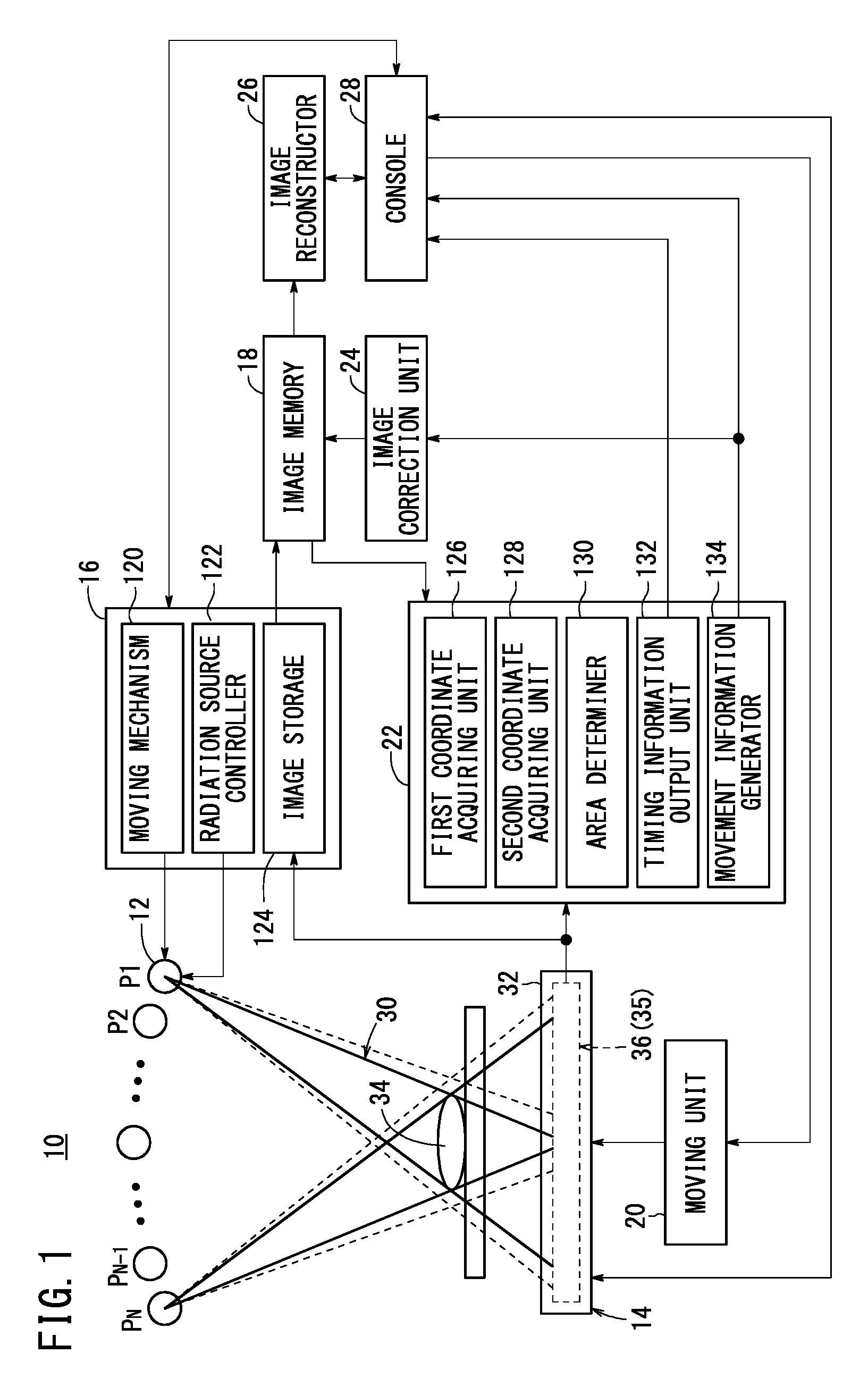
[0059]As shown in FIG. 1, the radiographic image capturing system 10 according to the present embodiment includes a radiation source 12, a radiation detecting device 14, a radiographic image acquiring unit 16, an image memory 18, a moving unit 20, a timing prediction unit 22, an image correction unit 24, an image reconstructor 26, and a console 28 (controller) for controlling the aforementioned components.

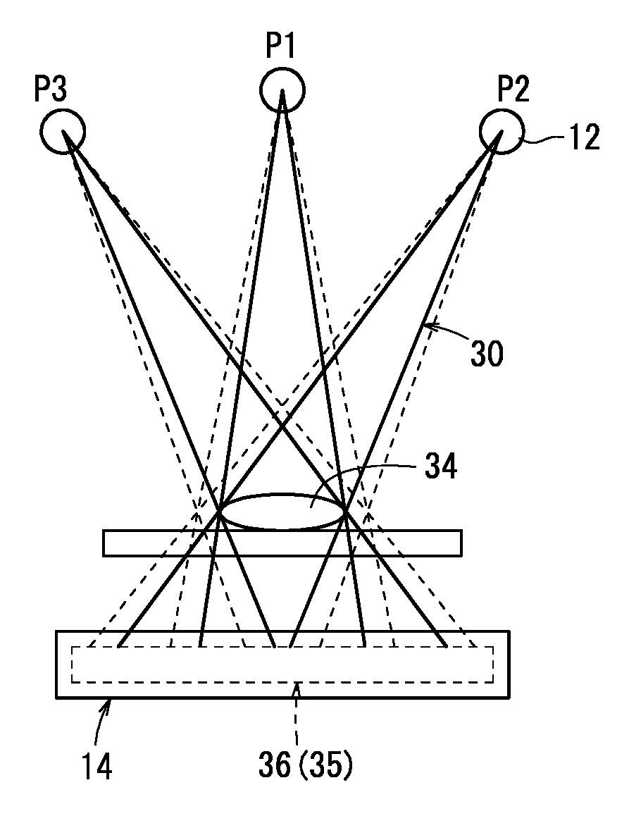
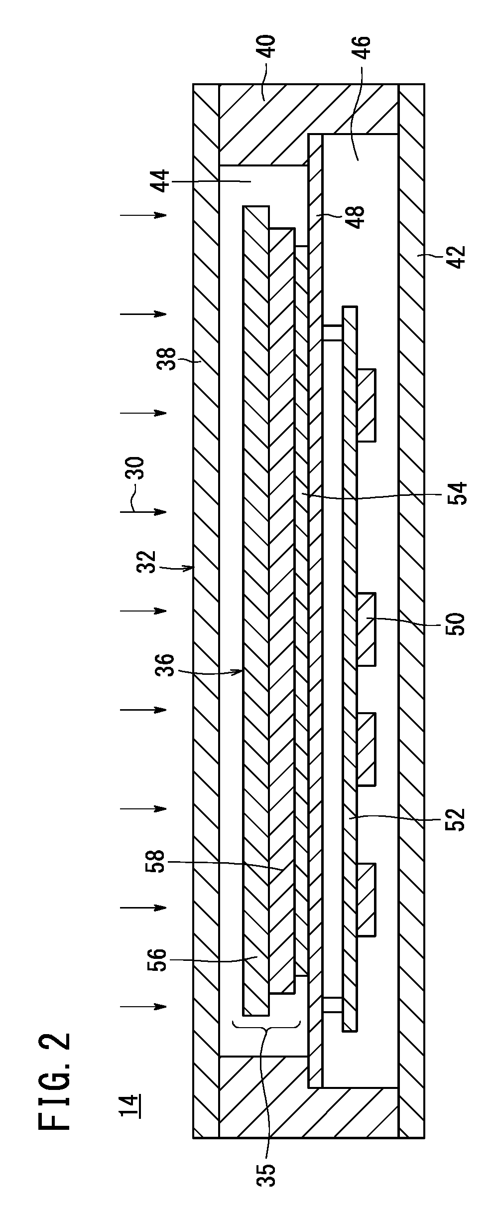
[0060]The radiation detecting device 14 includes a casing 32 made of a material that is permeable to radiation 30 emitted from the radiation source 12, and a radiation detector 36 (see FIG. 2) having a converter 35 for converting radiation 30 from the radiation source 12 that has passed at least through a subject 34.

[0061]As shown in FIG. 2, the casing 32 h...


PUM


Abstract

This radiation imaging system has a radiation source, a case, and a radiation detection device which is housed in the case, and is equipped with a radiation detector having a conversion unit that converts radiation from the radiation source, which has passed through at least a subject, to radiation image information, wherein a prediction is made as to whether the afterimage phenomenon has occurred in the conversion unit, and if it is predicted that the phenomenon has occurred, at least the conversion unit is moved.

Description

CROSS-REFERENCE TO RELATED APPLICATIONS AND PRIORITY CLAIM[0001]This application is a Continuation of International Application No. PCT / JP2012 / 066529 filed on Jun. 28, 2012, which was published under PCT Article 21(2) in Japanese, which is based upon and claims the benefit of priority from Japanese Patent Application No. 2011-146653 filed on Jun. 30, 2011, the contents all of which are incorporated herein by reference.TECHNICAL FIELD[0002]The present invention relates to a radiographic image capturing system having a radiation detecting device for converting radiation from a radiation source that has passed through a subject into radiographic image information. More particularly, the present invention relates to a radiographic image capturing system suitable for carrying out a tomosynthetic image capturing process to acquire a tomographic image according to radiography.BACKGROUND ART[0003]In the medical field, portable radiographic image capturing apparatus such as an FPD (Flat Pane...

Claims


Application Information

Patent Timeline
Patent Type & Authority Patents(United States)
IPC IPC(8): G01J1/42G01T1/20G01T1/17A61B6/02A61B6/00A61B6/04
CPCG01T1/17A61B6/025A61B6/4283A61B6/4452G01T1/2014A61B6/0407A61B6/4233
Inventor OHTA, YASUNORINAKATSUGAWA, HARUYASUNISHINO, NAOYUKIIWAKIRI, NAOTO
Owner FUJIFILM CORP
Why Eureka
Try Eureka