Substrate for mounting light emitting element, light emitting module and lighting apparatus

Inactive Publication Date: 2008-10-23
THE FUJIKURA CABLE WORKS LTD
View PDF14 Cites 15 Cited by
  • Summary
  • Abstract
  • Description
  • Claims
  • Application Information

AI Technical Summary

Benefits of technology

[0017]The substrate for mounting light emitting elements of the present invention has two or more conductive layers and insulating layer provided between each conductive layer that were formed on the outside of an enameled substrate, which is an enamel layer covering the surface of a core metal. It also has a conductive layer provided on the enamel layer side that links one end of the enameled substrate to the other end, and feeds power to a plurality of light emitting elements mounted in the longitudinal direction of the conductive layer. Also, a conductive layer on the surface of a protruding section provided at both ends of the enameled substrate extends and forms a connection with another substrate. As a result, the heat dissipating ability is good, and a plurality of light emitting element can be mounted with using conductive layers within the substrate and without running separate wires. Moreover, connection with another substrate can be easily made, and a substrate for mounting light emitting elements with excellent extensibility can be provided.
[0018]Also, the light emitting module and lighting apparatus of the present invention make use of the substrate for mounting light emitting elements of the present invention, and are mounted with a plurality of light emitting elements using the conductors in the substrate without running separate wires; therefore, they can be made compact and provided at an economical cost. Moreover, connection with a separate light emitting module through the connection terminal of the substrate can be made easily; so a plurality of links can be made longitudinally and transversely without a gap, thus enabling lighting apparatus of large area to be realized easily.

Problems solved by technology

However, if a large number of light emitting modules is assembled, running wires separately from the substrate, whereupon light emitting modules are mounted, becomes complicated and leads to an increase in the cost.
Also, if the wires are stored within a lighting apparatus to ensure that the wiring does not receive external damage, then design restrictions will be imposed on the lighting apparatus because of this storage space.
This leads to the problem of increase in the size of the apparatus.

Method used


Image

  • Substrate for mounting light emitting element, light emitting module and lighting apparatus
  • Substrate for mounting light emitting element, light emitting module and lighting apparatus
  • Substrate for mounting light emitting element, light emitting module and lighting apparatus

Examples


Embodiment Construction

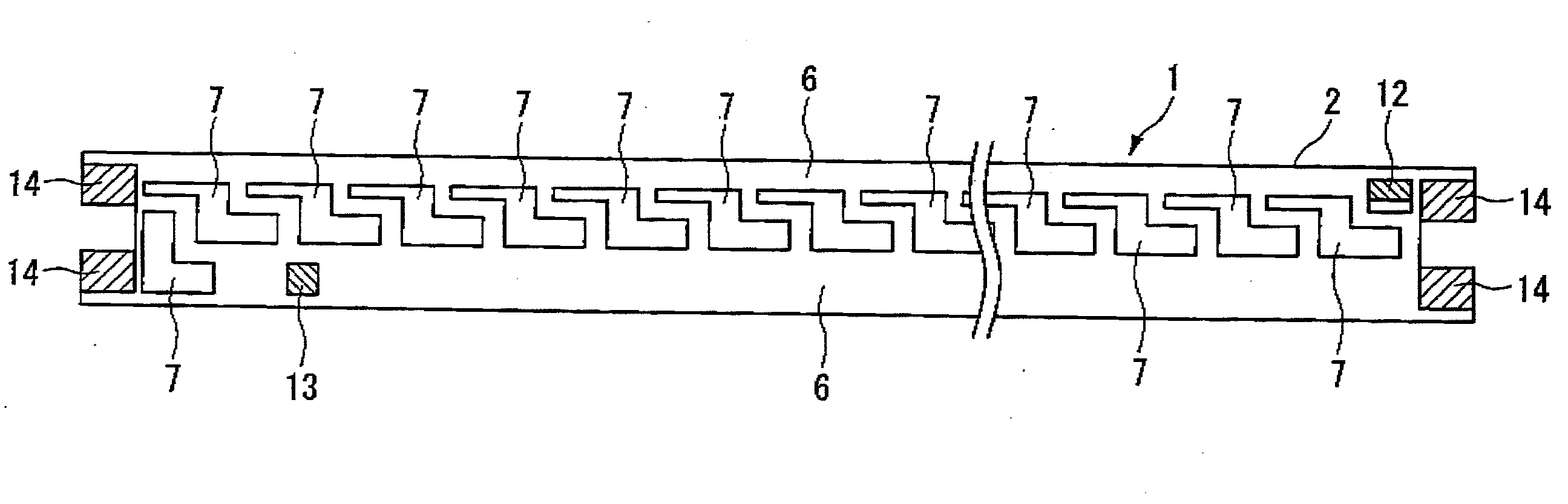
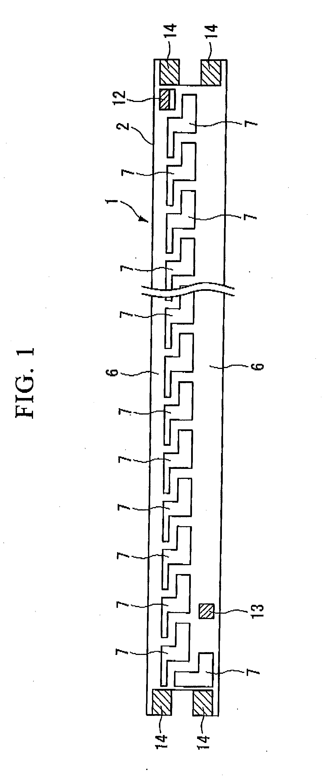
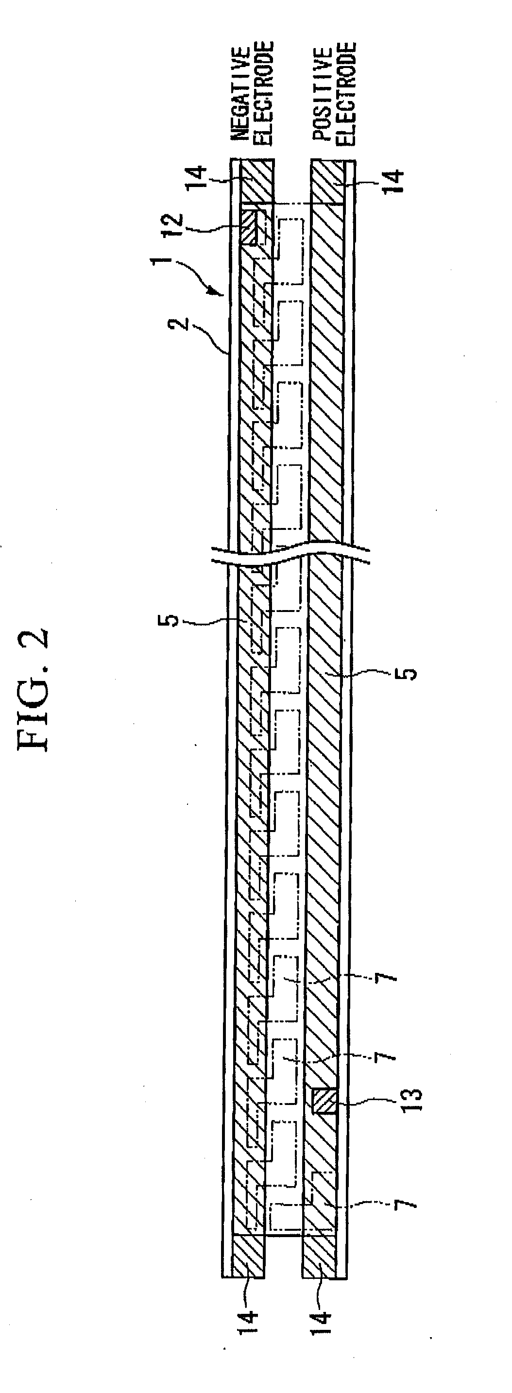
[0012]A first aspect of the present invention provides a substrate for mounting light emitting elements is provided, comprising an enameled substrate in which the surface of a core metal is covered with an enamel layer; wherein two or more conductive layers and an insulating layer provided between every two of the conductive layers are formed on the outside of the enameled substrate; wherein the conductive layer disposed at an enamel layer side is provided extending through the enameled substrate from one end to the other end such that it feeds power to a plurality of light emitting elements mounted along a longitudinal direction of the conductive layer; and wherein the conductive layer extends on the surface of a protruding section provided at both ends of the enameled substrate and forms a connection with another substrate.

[0013]In a non-limiting embodiment, in the substrate for mounting light emitting elements according to the present invention, at least part of the conductive la...


PUM


Abstract

A substrate for mounting light emitting elements having two or more conductive layers and an insulating layer provided between each conductive layer, which are formed on the outside of an enameled substrate, the enameled substrate being an enamel layer covering the surface of a core metal. The conductive layer provided on the enamel layer side links one end of enameled substrate to the other end, and feeds power to a plurality of light emitting elements mounted in the longitudinal direction of the conductive layer. Furthermore, the conductive layer on the surface of a protruding section provided at both ends of the enameled substrate extends and forms a connection with another substrate. A light emitting module is formed by mounting light emitting elements on the substrate.

Description

CROSS REFERENCE TO RELATED APPLICATION[0001]This application claims priority from PCT Application No. PCT / JP2006 / 311614, filed Jun. 9, 2006 and from Japanese Application No. 2005-172202 filed Jun. 13, 2005, which applications are incorporated herein by reference.TECHNICAL FIELD[0002]The present invention relates to a substrate for mounting a plurality of light emitting elements, such as light emitting diodes (hereafter referred to as “LED”) thereon, especially applications thereof such as lighting, substrate for mounting light emitting elements that can supply current to a plurality of light emitting elements by only conductive layers in the substrate without running separate wiring while ensuring heat dissipating ability when light emitting elements are mounted at a high density, light emitting module mounted with light emitting elements mounted on said substrate, and lighting apparatus provided with such light emitting modules.BACKGROUND ART[0003]Adequate brightness cannot be obta...

Claims


Application Information

Patent Timeline
IPC IPC(8): H01L33/00H01L33/64
CPCF21K9/00H01L33/64H05K1/053H05K1/117H05K2201/10106H01L2224/45144H01L2224/73265H01L2224/48091H01L2924/00014H01L2924/00
Inventor MASUKO, KOICHIRO
Owner THE FUJIKURA CABLE WORKS LTD
Why Eureka
Try Eureka