

Flip-chip light-emitting module
- Summary
- Abstract
- Description
- Claims
- Application Information
AI Technical Summary
Benefits of technology
Problems solved by technology
Method used
Image

Examples
first embodiment
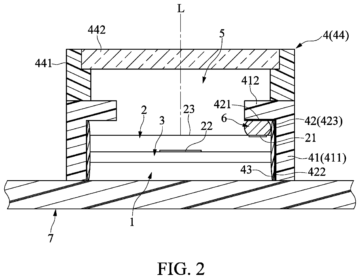
[0032]Referring to FIG. 2, a first embodiment of the present disclosure provides a flip-chip light-emitting module adapted for mounting on a main circuit board 7 in order to cooperate with the main circuit board 7, or adapted for electrically connecting to an external power source and being driven. The method and field of use are not the focus of the present invention, thus they are not described in detail herein.
[0033]The flip-chip light-emitting module includes a thermal dissipation substrate 1, a light-emitting chip 2, a conductive adhesive layer 3, a package assembly 4, and a conductor 6.
[0034]The thermal dissipation substrate 1 is selected from the group consisting of an albumin substrate, a copper substrate, and any substrates having good heat-dissipating or heat-conductive abilities. One side of the thermal dissipation substrate 1 is adapted for electrically connecting to the main circuit board 7, and another side of the thermal dissipation substrate 1 is connected to light-e...
second embodiment
[0052]Referring to FIG. 7, a second embodiment of the present disclosure is roughly the same as the first embodiment, and the main difference between the present embodiment and the first embodiment is that the light-emitting chip 2 includes two top conductive contacts 21 and two bottom conductive contacts 22, and correspondingly the thermal dissipation substrate 1 includes two separated plates 11. The adjacent plates 11 together define a thermal dissipation channel 12.
[0053]The thermal dissipation substrate 1 may include two, three, or more than four plates 11. The number of the plates 11 can be adjusted according to particular implementations. In this embodiment, the number of the plates 11 is two, and the number of the thermal dissipation channel 12 is one.
[0054]Therefore, the second embodiment has the same advantages of the first embodiment, and further discloses another feasible structure of the light-emitting chip 2 that includes multiple bottom conductive contacts 22. Correspo...
third embodiment
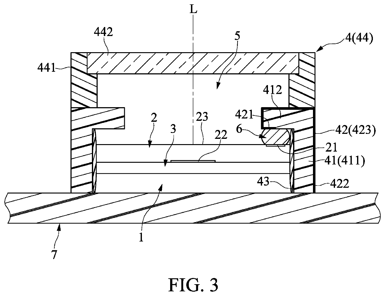
[0056]Referring to FIG. 8, a third embodiment of the present disclosure is roughly the same as the first embodiment, and the main difference between the present embodiment and the first embodiment is that the lens unit 44 does not include the support 441 (shown in FIG. 2), and the lens 431 is directly disposed on the frame 41, that is, the frame 41 also has the function of the support 441.
[0057]Removing the support 441 (shown in FIG. 2) can further decrease the height of the flip-chip light-emitting module and reduce the overall size. Therefore, the third embodiment has the advantages of the first embodiment, and can further decrease the size of the flip-chip light-emitting module.
[0058]Furthermore, the configurations of the conductive contacts 21, 22 of the light-emitting chip 2 are the same as shown in the first embodiment, thus users can adjust them according to their actual needs without any limitation. However, for ease of explanation, the light-emitting chip 2 of the present e...
PUM
 Abstract
Description
Claims
Application Information