Lighting device and display device

Inactive Publication Date: 2020-08-20
SHARP KK
View PDF7 Cites 0 Cited by
  • Summary
  • Abstract
  • Description
  • Claims
  • Application Information

AI Technical Summary

Benefits of technology

The technology described in this patent allows for the creation of thin lighting and display devices that produce high levels of light and have a reduced width frame. Additionally, the technology has good heat dissipation capabilities.

Problems solved by technology

Namely, it is difficult to achieve both of high luminance and reduced thickness.
Therefore, if the backlight unit is used continuously for a long time, the temperature of the LEDs may increase excessively and the display quality of the display panel may be adversely affected as follows.
The light emission condition of the LEDs may become unstable, or the light guide plate may be distorted and brightness and luminance may be varied.
However, in the above configuration, the LED boards 2 are arranged in the direction along the front and back surfaces 4, 5 of the light guide plate 3 and therefore, the frame width cannot be reduced easily.
Furthermore, in the configuration including the two LED boards the number of components such as the connectors 6 is increased and a cost is also increased.

Method used


Image

  • Lighting device and display device
  • Lighting device and display device
  • Lighting device and display device

Examples


first embodiment

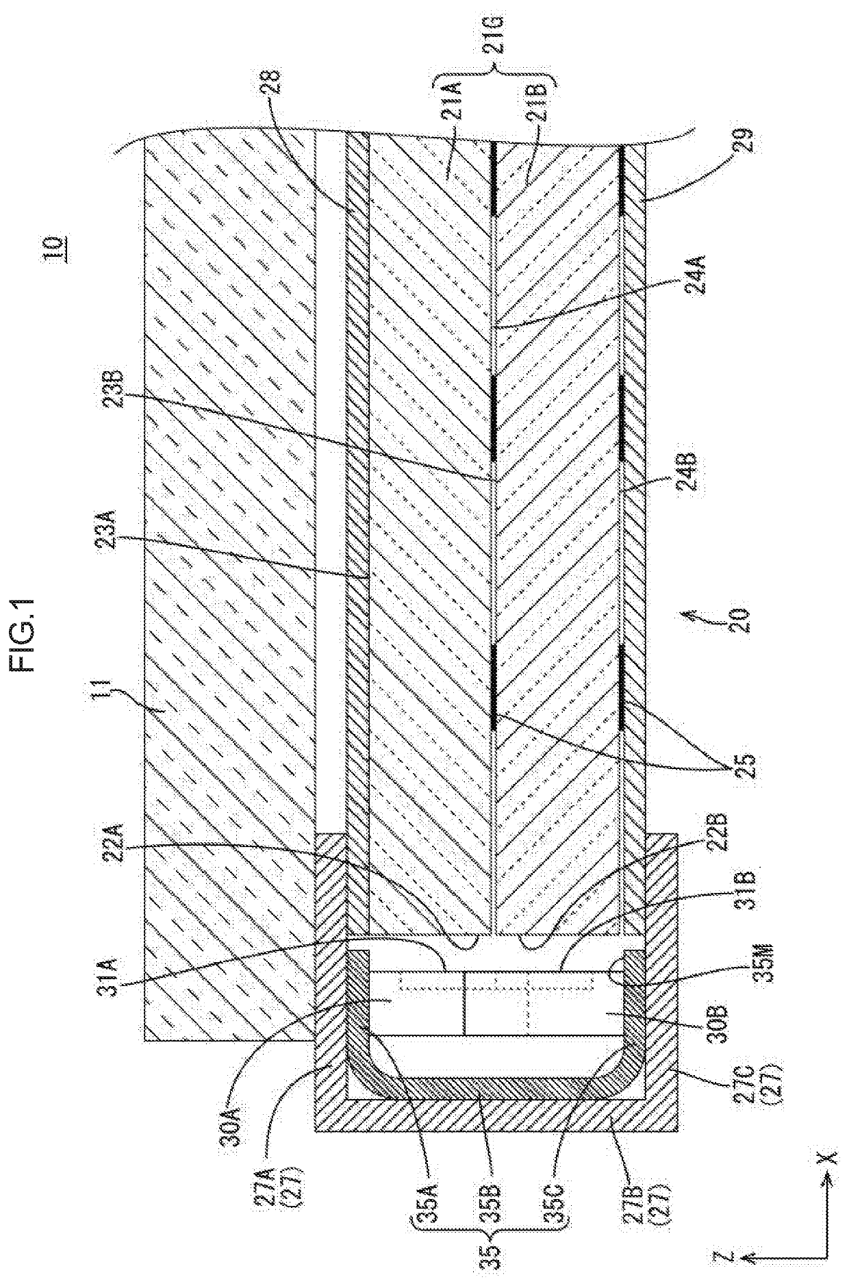
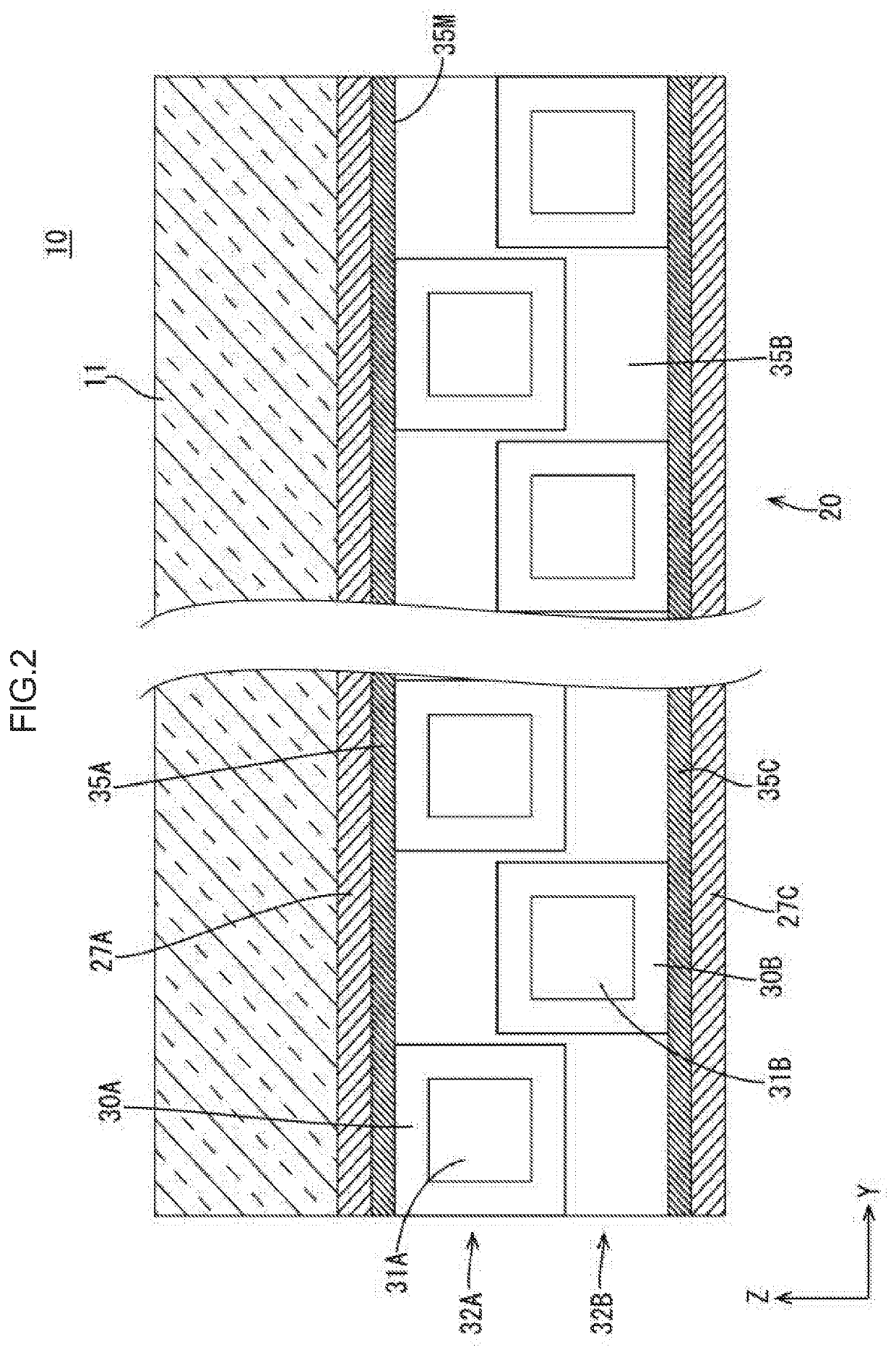
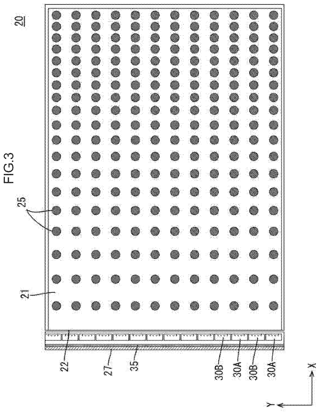
[0039]A first embodiment will be described with reference to FIGS. 1 to 4. In the section, a liquid crystal display device 10 (one example of a display device) including a liquid crystal panel 11 as a display panel will be described as examples. X-axis, Y-axis and Z-axis may be present in the drawings and each of the axial directions represents a direction represented in each drawing. A vertical direction is determined with reference to FIG. 1 and an upper side and a lower side in FIG. 1 correspond to a front side and a back side, respectively. One of the same components is provided with a symbol and other ones are not provided with the symbol.

[0040]The liquid crystal display device 10 has a rectangular flat box overall shape and includes a liquid crystal panel 11 (one example of a display panel) displaying an image and a backlight unit 20 (one example of a lighting unit) that is disposed on a back side with respect to the liquid crystal panel 11 and supplies light to the liquid cry...

second embodiment

[0081]Next, a second embodiment will be described with reference to FIG. 5. In the following, configurations that differ from those in the first embodiment will be described and the components same as those in the first embodiment are provided with the same symbols and will not be described.

[0082]A backlight unit 120 in this embodiment differs from that in the first embodiment in a material of a base member of an LED board 135. Other configurations are same as those of the first embodiment. Specifically, the base member of the LED board 135 in this embodiment is made of metal material having high thermal conductivity such as gold, silver, copper, aluminum, and iron. Among them, silver has highest thermal conductivity and high reflectance; however, copper or aluminum is preferably used in view of a material cost and easiness of bending processing.

[0083]According to the backlight unit 120 and a liquid crystal display device 110 in the present embodiment, the operations and effects sim...

third embodiment

[0085]Next, a third embodiment will be described with reference to FIG. 6. In the following configurations that differ from those in the first embodiment will be described and the components same as those in the first embodiment are provided with the same symbols and will not be described.

[0086]A backlight unit 220 in this embodiment differs from that in the first embodiment in a configuration of the light source. Other configurations are similar to those in the first embodiment.

[0087]The present embodiment includes color light sources that emit light of single color of each of the three primary colors that are red, green, blue (R / G / B). The color light source includes several kinds of types such as a RGB 3-in type, a RGB independent package type, and a RGB exciting type. The color light source of the RGB 3-in type includes three kinds of LED chips of R / G / B included in one package and sealed with resin. The color light source of the RGB independent package type includes the three kin...


PUM


Abstract

A lighting device includes light sources, a light source board, and a light guide plate having a light entering edge surface and plate surfaces. The light sources configure light source rows in each of which the light sources are arranged such that the light emitting surfaces are opposite the light entering edge surface. The light source board includes a first mounting section having the mounting surface opposite one plate surface, a second mounting section having the mounting surface opposite another plate surface, and connection section connecting the first and second mounting sections to be opposite and away from the light entering edge surface. Among the light source rows, the light sources of a first light source row are mounted on the first mounting section and the light sources of a second light source row are mounted on the second mounting section.

Description

CROSS REFERENCE TO RELATED APPLICATION[0001]This application claims priority from U.S. Provisional Patent Application No. 62 / 808,079 filed on Feb. 20, 2019. The entire contents of the priority application are incorporated herein by reference.TECHNICAL FIELD[0002]The technology described herein relates to a lighting device and a display device.BACKGROUND ART[0003]A liquid crystal display device including a liquid crystal panel is used as a display device of mobile terminal devices such as a tablet-type personal computer, a digital camera, and a smartphone and a television. Since the liquid crystal panel does not emit light, the liquid crystal panel needs to use external light to display an image. Therefore, this type of display device includes a lighting unit (a so-called backlight unit) that supplies light to the liquid crystal panel in addition to the liquid crystal panel. The backlight unit is disposed on a back surface side of the liquid crystal panel and is configured to supply ...

Claims


Application Information

Patent Timeline
IPC IPC(8): G02F1/13357G02F1/1333F21V8/00
CPCG02F1/133603G02B6/0073G02F1/133382G02F1/133606G02F2001/133607G02B6/0078G02B6/0068G02B6/0076G02B6/0083G02B6/009G02F1/133607
Inventor TAKASE, KENJI
Owner SHARP KK
Why Eureka
Try Eureka