Lighting device, display device, and method of manufacturing lighting device

Active Publication Date: 2019-07-09
SHARP KK
View PDF14 Cites 0 Cited by
  • Summary
  • Abstract
  • Description
  • Claims
  • Application Information

AI Technical Summary

Benefits of technology

[0034]According to the present invention, brightness is le

Problems solved by technology

However, in the configuration of the edge light-type backlight device described in Patent Document 1, the light entering the light guide plate is likely to leak from the light guide plate through an edge surface of the light guide plate opposite from the light entrance surface (hereinafter, an op

Method used


Image

  • Lighting device, display device, and method of manufacturing lighting device
  • Lighting device, display device, and method of manufacturing lighting device
  • Lighting device, display device, and method of manufacturing lighting device

Examples


Example

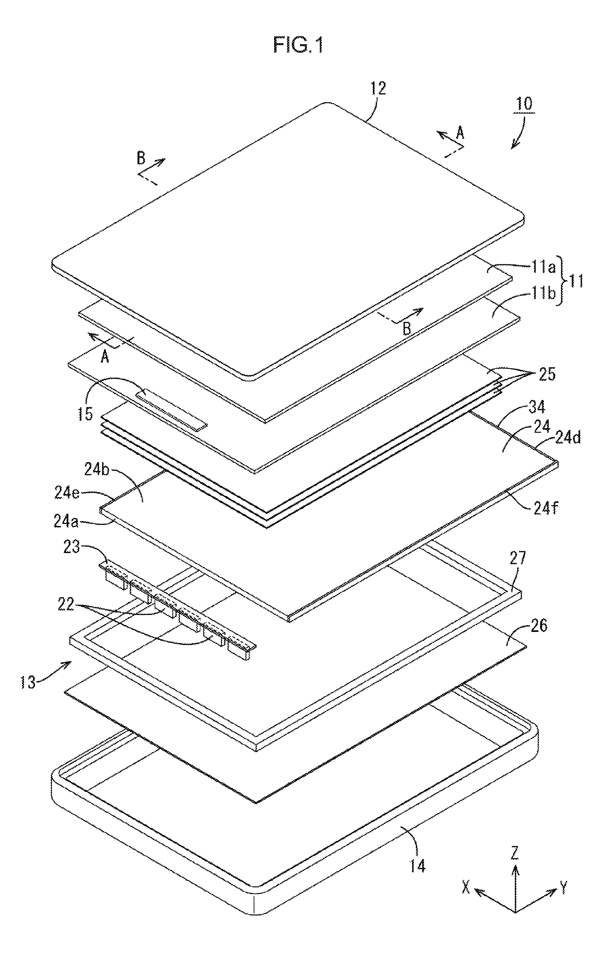
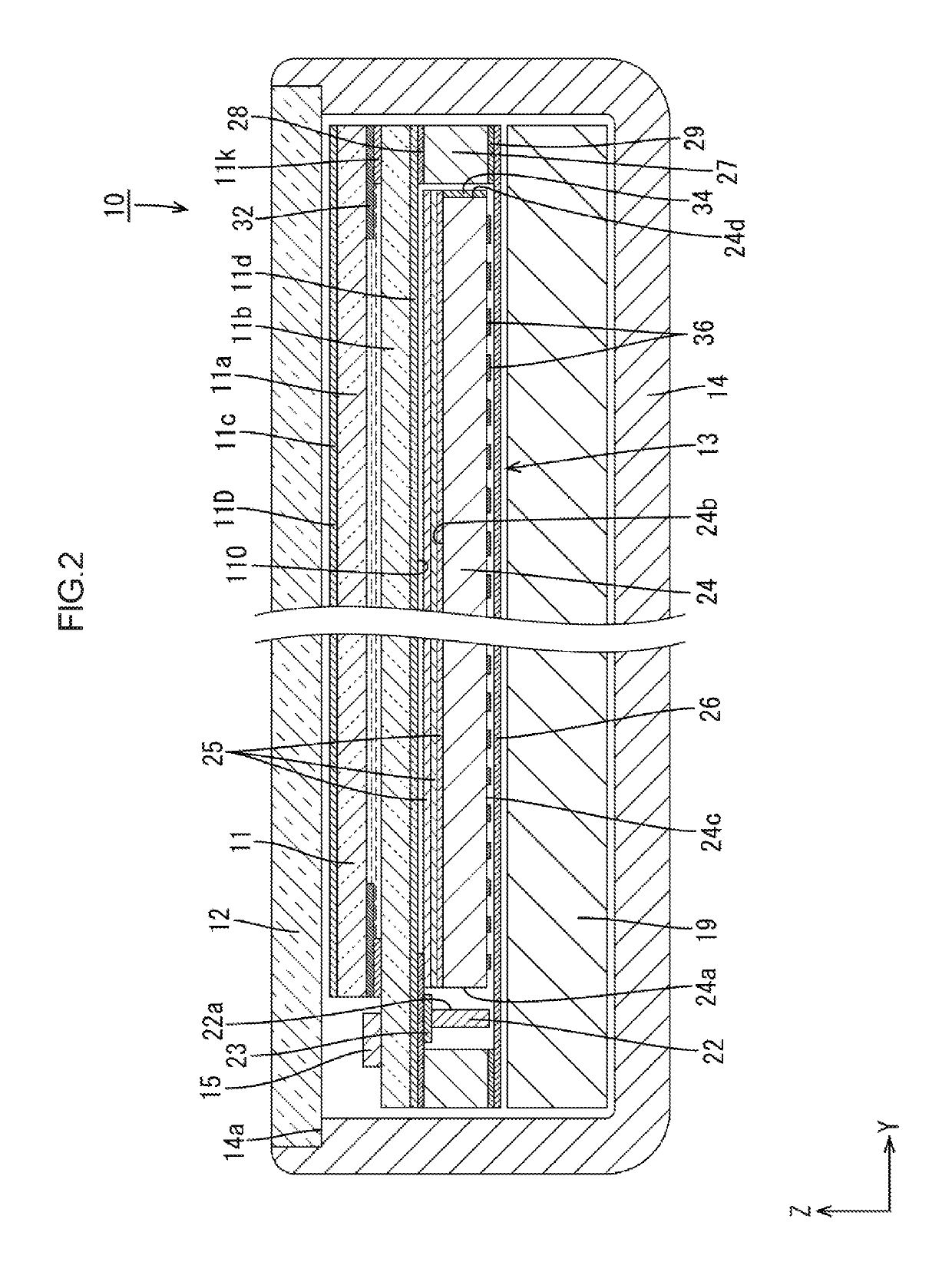
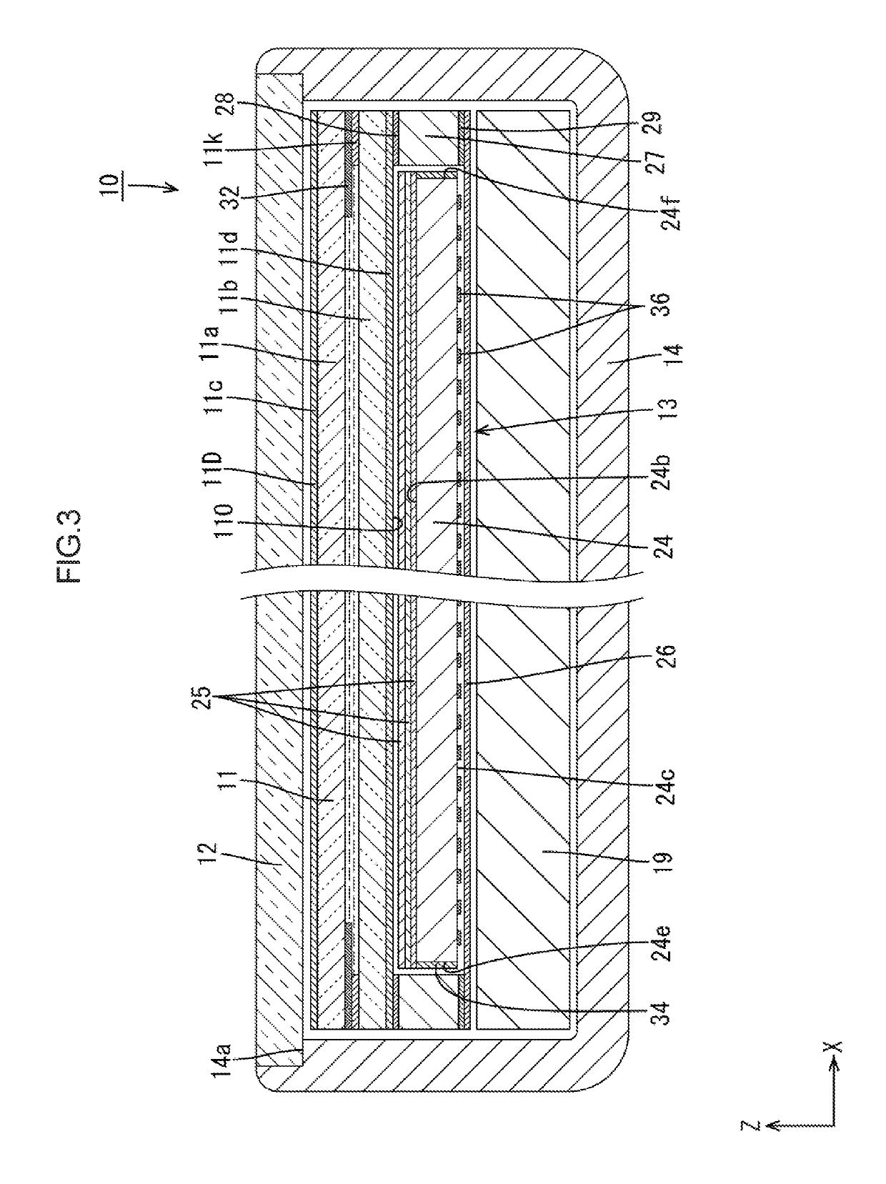
[0063]A first embodiment of the present invention will be described with reference to FIGS. 1 to 8. A backlight device 13 and a liquid crystal display device 10 including the backlight device will be described as an example. X-axis, the Y-axis and the Z-axis may be present in the drawings. An upper side and a lower side in FIG. 3 correspond to a front side and a back side of the backlight device 13, respectively.

[0064]FIG. 1 is an exploded perspective view of the liquid crystal panel display device 10 according to the first embodiment. As illustrated in FIG. 1, the liquid crystal display device 10 has a vertically-long quadrilateral (or rectangular) overall shape. The liquid crystal panel display device 10 includes a liquid crystal panel (a display panel) 11, a cover panel 12, and the backlight device (a lighting device) 13. The liquid crystal panel 11 has a front side plate surface that is a display surface 11D displaying images and a rear side plate surface that is an opposite sur...

Example

Second Embodiment

[0103]Next, a second embodiment of the present invention will be described with reference to FIG. 9. In the following embodiments, same symbols or numbers as the first embodiment are applied to parts same as those in the first embodiment and they will not be described in detail (regarding configurations or effects). In a backlight device 113 of the present embodiment, configurations of a light reflecting portion 134 and a light blocking layer 132 differ from those of the light reflecting portion 34 and the light blocking layer 32 of the first embodiment.

[0104]The opposite edge surface 24d, the edge surface 24e, and the edge surface 24f are directly coated with mirror ink to form a coating film of the light reflecting portion 134 having a mirror surface. Light travelling within the light guide plate 24 toward the edge surfaces 24d, 24e, 24f is reflected by the light reflecting portion 34 with mirror surfaces and travels toward the inside of the light guide plate 24.

[...

Example

Third Embodiment

[0109]Next, a third embodiment of the present invention will be described with reference to FIG. 10. In the present embodiment, a backlight device 213 will be described. In the backlight device 213 of the present embodiment, a light guide plate 224 and a frame 227 have configurations different from those of the light guide plate 24 and the frame 27 of the first embodiment.

[0110]The light guide plate 224 has a rectangular plan view shape as a whole and has four corners each having a round corner shape. In other words, the light guide plate 224 includes curved edge surfaces 24d1, 24d2 having curved planar shape. The curved edge surface 24d1 connects the edge surfaces 24e and 24d, and the curved edge surface 24d2 connects the edge surfaces 24d and 24f. In the present embodiment, the light reflecting portion 34 is formed on the edge surfaces 24e, 24f, and the opposite edge surface 24d including the curved edge surfaces 24d1, 24d2.

[0111]The frame 227 has a frame shape ext...


PUM


Abstract

A backlight device 13 includes LEDs 22, a light guide plate 24, and a light reflecting portion 34. The light guide plate 24 is a plate member and includes a light entrance surface 24a, an opposite edge surface 24d, and a light exit surface 24b. The light entrance surface 24a is an edge surface of the plate member and opposite the LEDs 22 and light emitted by the LEDs 22 enters the light guide plate 24 through the light entrance surface. The opposite edge surface 24d is another edge surface of the plate member that is on an opposite side from the light entrance surface 24a. The light exit surface 24b is a plate surface of the plate member and the light entering through the light entrance surface 24a exits the light guide plate 24 through the light exit surface. The light reflecting portion 34 is disposed on at least the opposite edge surface 24d and reflecting light travelling within the light guide plate 24 toward the opposite edge surface 24d.

Description

TECHNICAL FIELD[0001]The present invention relates to a lighting device, a display device, and a method of manufacturing a lighting device.BACKGROUND ART[0002]Liquid crystal panels have been widely used as display panels for displaying images in display devices of electronic devices such as handheld terminals (for example, smartphones and tablet computers). Such a display device includes the liquid crystal panel and a backlight device (a lighting device) that supplies light to the liquid crystal panel.[0003]An example of the backlight device is described in Patent Document 1 and includes a light guide plate made of transparent plate member, and a light source (for example, LEDs) that is arranged opposite an edge surface of the light guide plate. Such a device is a backlight device of an edge light type (or a side light type). Light emitted by the light source of the backlight device enters the light guide plate through an edge surface of the light guide plate opposite the light sour...

Claims


Application Information

Patent Timeline
IPC IPC(8): F21V8/00G02F1/1333
CPCG02B6/0033G02B6/0055G02B6/0065G02B6/0088G02B6/0076G02F1/133308G02B6/0061
Inventor WATANABE, HISASHIYUKI, RYUZOMURATA, MITSUHIRO
Owner SHARP KK
Why Eureka
Try Eureka