Brightness preserving fiber beam combiner for reduced nonlinearities and intense radiation damage durability

a fiber beam and combiner technology, applied in the field of brightness preserving fiber beam combiners, can solve the problems that devices cannot provide all of these capabilities simultaneously, and achieve the effects of avoiding or reducing the “refraction index hole”, accurate parabolic refraction index profiles, and severe brightness degradation

Active Publication Date: 2017-03-23
STATE OF ISRAEL - SOREQ NUCLEAR RES CENT
View PDF1 Cites 0 Cited by
  • Summary
  • Abstract
  • Description
  • Claims
  • Application Information

AI Technical Summary

Benefits of technology

[0010]Another advantage of the invention is avoiding or reducing the “refraction index hole” at the center of the GI core. This was evidently caused by the traditional fabrication method of GI fibers, based on gradually evaporating high-index material on the inner walls of a hollow silica tube and then collapsing both to the final fiber diameter using heat.
[0011]Another embodiment of the invention creates an accurate parabolic refraction index profile. Previous attempts in the prior art created a gradual index profile, that is close to being “parabolic”, and even that only at the inner diameter of the fiber's core (typically, the central ⅓ of the core). Once a signal is launched out of this regime, where deviation from perfect parabolic index profile may occur, BPP is hardly kept, and brightness is severely deteriorating if launched close to the core's edge. In the present invention, there is a full parabolic profile across the whole core's region, thereby assuring a strict BPP preservation of whatever signal is launched into the GI core, as long as it is within the acceptance solid-angle (NA) of the fiber.

Problems solved by technology

Prior art combining devices cannot provide all of these capabilities simultaneously, because one of the limitations (brightness level / nonlinearities / damage) would occur once a multi-Kw beam is transported.

Method used


Image

  • Brightness preserving fiber beam combiner for reduced nonlinearities and intense radiation damage durability

Examples


Embodiment Construction

[0015]In contrast to the prior art, the present invention relates to a large combiner whose waist width can confine a few-mode beam to a level that it is compressed to give the lowest BPP value, yet is enough wide such that it maintains intensity levels that are factors below the silica bulk damage. This dielectric / bulk damage threshold is mostly referred to as 5 w / μm2 and 10 w / μm2 for exit facet (silica-air boundary) and internal glass (i.e. material continua), respectively (Dawson et-al, Optics Express (2010)).

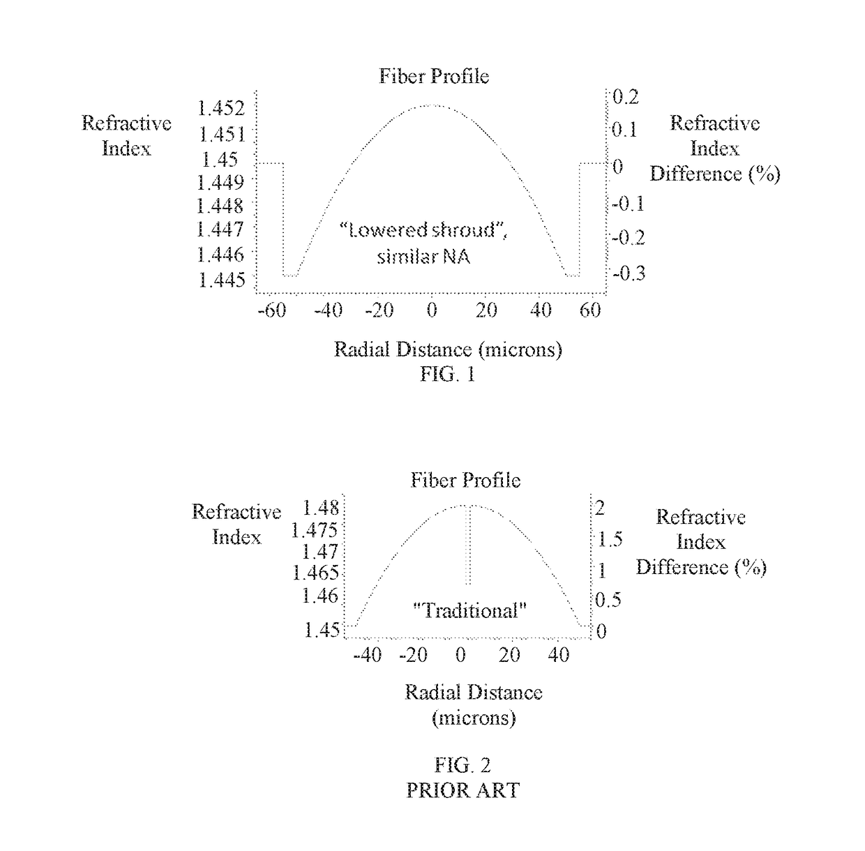
[0016]Traditional GI (graded-index) fiber fabrication is done by gradually doping of materials into the core, that, as a side effect, have high nonlinearity gain, of which SRS (stimulated Raman scattering) becomes a major challenge. A very common material used for index increasing is GeO2. However, the most prominent characteristic of this addition is its Raman Gain, which is ˜8-9 times higher than of pure silica (gR(Si—O2)≈1.05e−13 m / w, with spectral gain peak at stokes wav...


PUM


Abstract

Method for adapting a fiber beam combiner to transmit at least 20 kW of optical power without noticeable bulk material damage mechanism effect and destructive nonlinearities, the method comprising: connecting an adiabatic beam combiner with a splice connection to an input facet of a graded index fiber which has a core doped with an index increasing material, further comprising the step(s) of: restricting the numerical aperture of the graded index fiber, and / or selecting the index increasing material with a Raman gain lower than that of Ge02 such as Al2O3 or Y2O3, and / or placing a shroud tube around the graded index fiber core, said shroud tube comprising a fluorine-doped silica tube.

Description

FIELD OF THE INVENTION[0001]The present invention relates to a novel fiber beam combining device that is suitable for handling very high optical powers. When operated, it shows low nonlinearities and high radiation and thermal damages durability, with respect to prior art devices. Moreover, it can either preserve the brightness obtained from several mutually incoherent incident optical beams, or even enhance brightness by a factor of N, if N mutually coherent beams are used.BACKGROUND OF THE INVENTION[0002]Multimode (MM) commercially available intra-fiber combiners are nowadays very common devices. If operated at their ultimate performance, they can approach output brightness preservation, in parallel with nearly perfect power transmission. However, only poor (i.e. high value of) spatial beam-parameter-product (BPP), a quantitative measure of brightness level, can be obtained, and therefore these devices are not suited for directed radiation applications. (See, for example, U.S. Pat...

Claims


Application Information

Patent Timeline
Patent Type & Authority Applications(United States)
IPC IPC(8): G02B6/42G02B6/255G02B6/028
CPCG02B6/4296G02B6/255G02B6/0281G02B6/0288G02B6/03627G02B6/2856
Inventor SHAMIR, YARIV
Owner STATE OF ISRAEL - SOREQ NUCLEAR RES CENT
Why Eureka
Try Eureka