

Probe retention arrangement
a technology of retaining apparatus and probe, which is applied in the direction of metal working apparatus, instruments, manufacturing tools, etc., can solve the problems of insufficient geometry or method of holding probes that can address a dense array of pads, no apparatus or method that combines the requisite characteristics in a single probe card or testing apparatus, etc., and achieve precise dimensional tolerances and opening profiles
- Summary
- Abstract
- Description
- Claims
- Application Information
AI Technical Summary
Benefits of technology
Problems solved by technology
Method used
Image

Examples
Embodiment Construction
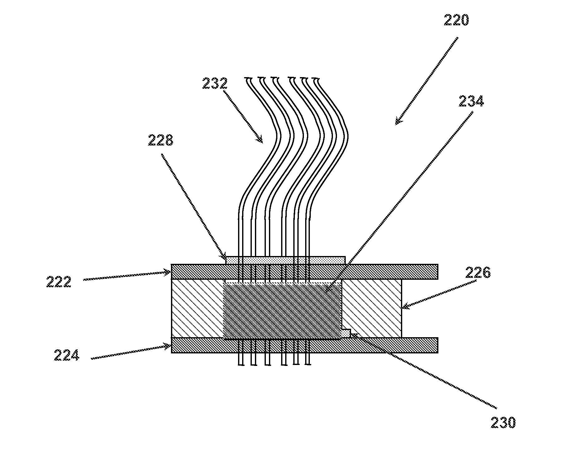
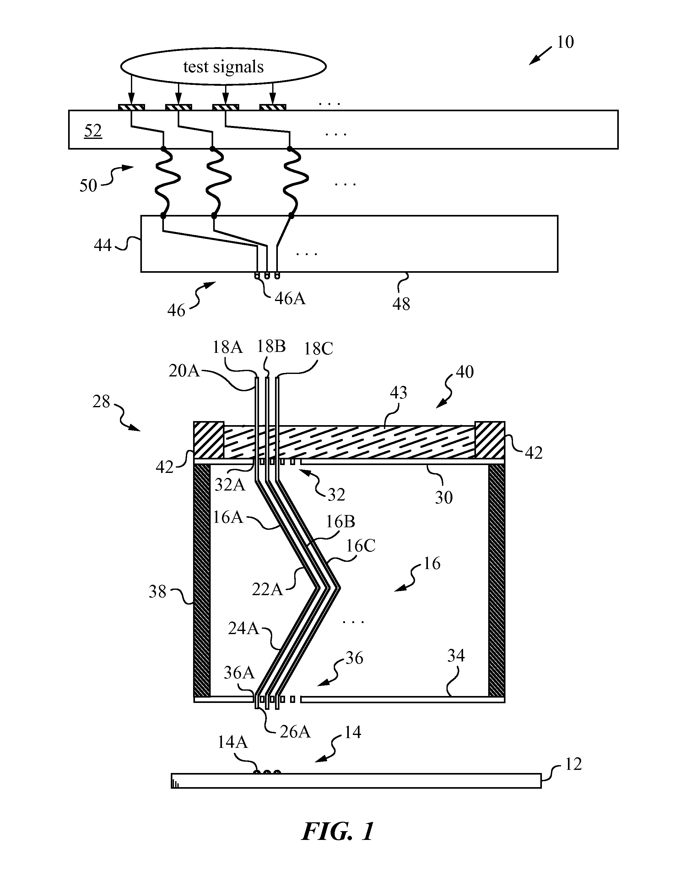
[0045]The present invention will be best understood by first reviewing an apparatus 10 of the invention as shown in the diagram of FIG. 1. Apparatus 10 can be employed in a probe card or other electrical testing equipment for testing a device under test (DUT) 12. Frequently, DUT 12 is an integrated circuit on a wafer that requires testing prior to dicing. Alternatively, DUT 12 is an electronic device or circuit that is already mounted. The functionality of DUT 12 is verified by applying test signals to a number of its bumps or pads 14.
[0046]Apparatus 10 has a number of probes 16 arranged in an array and designed for establishing electrical contact with pads or bumps 14. Typically, the number of probes 16 is large and their spacing or pitch is very small, e.g., on the order of several microns. For clarity, only three probes 16A, 16B, 16C are illustrated. The construction of all probes 16 is analogous and will be explained by referring explicitly to probe 16A.
[0047]Probe 16A has conne...
PUM
| Property | Measurement | Unit |
|---|---|---|
| diameter | aaaaa | aaaaa |
| diameter | aaaaa | aaaaa |
| diameter | aaaaa | aaaaa |
Abstract
Description
Claims
Application Information