Pressure sensor

a pressure sensor and pressure sensor technology, applied in the field of sensors, can solve the problems of insufficient support or failure to maintain the bandage in place, negative consequences on the healing process, and patients' discomfort or harm, and achieve the effects of accurate pressure profile, quick and accurate response to pressure changes, and convenient us

Active Publication Date: 2015-12-08
SFH OXFORD
View PDF2 Cites 7 Cited by
  • Summary
  • Abstract
  • Description
  • Claims
  • Application Information

AI Technical Summary

Benefits of technology

[0009]The present invention is based on a realisation of the need for a simple, single-use, disposable device that can aid in the placement of graduated compression bandages, to readily achieve a correct compression profile up the leg.
[0010]According to one aspect of the present invention, a pressure sensor comprises an elongate strip having a plurality of pressure-sensing pads arranged along its length, the strip further comprising an independent connection to each pad, whereby the pressure applied to each pad can be determined independently. In particular, a characteristic feature of the present invention is that each pad is inflatable to form an expanded pad or dome protruding above the surface of the strip, and deflatable. Deflation can be achieved by the application of negative pressure that can be maintained during withdrawal. This means that a dome formed by inflation can be drawn down and held below the upper surface of the strip, so that it does not impede removal of the sensor from an applied bandage.
[0013]A device of the invention can provide one or more of various advantages. It can be applicable to all shapes and lengths of leg, easy to use, give an accurate pressure profile over a range of compression levels, respond to pressure changes quickly and accurately, be easily removed, and be economic to produce. It can make the process of graduated compression bandaging sufficiently straightforward that prolonged training in the technique is not necessary. Anyone from health care assistant up to consultant surgeon could use the device to achieve a correct technique in moments.

Problems solved by technology

The application of excessive pressure can cause discomfort or harm to a patient.
The application of insufficient pressure has negative consequences on the healing process, and may also provide insufficient support or fail to maintain the bandage in place.
These factors make it exceptionally difficult to get the graduated compression profile absolutely correct, so as to maximise the chance that the ulcer eventually heals.
However, the problem of ensuring correct usage remains.
The device is however dependent on the use of a QTC material, and has disadvantages including (i) the difficulty of producing a homogeneous composite material such that the electrical response is uniform throughout the device, and (ii) the fact that the magnitude of the obtained signal from such a sensor may be low and also compromised by the level of noise, and (iii) the likelihood that incorrect measurement will be recorded if the bandage is pulled laterally across the device.
In addition, if a raised area is used to obtain good results, it may be difficult to remove the device from a bandage.
Furthermore, the device may be uneconomical as a single-use, disposable product.

Method used


Image

  • Pressure sensor
  • Pressure sensor
  • Pressure sensor

Examples


example 1

Pneumatic Sensor

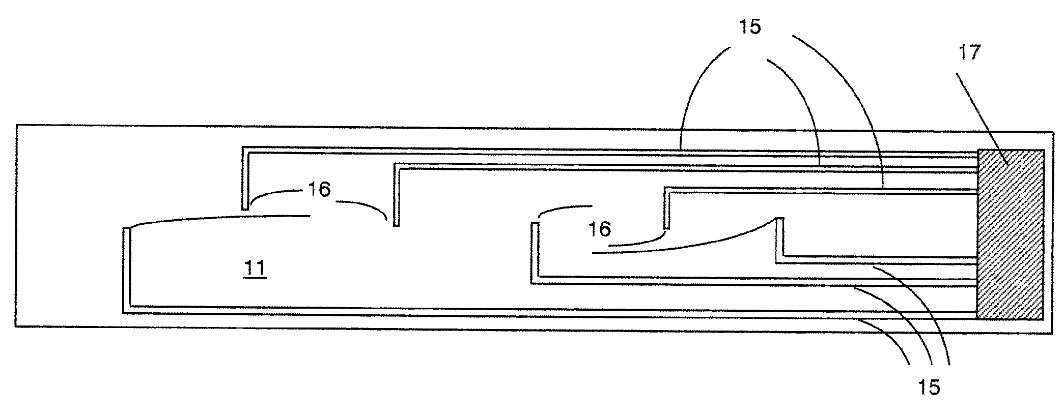
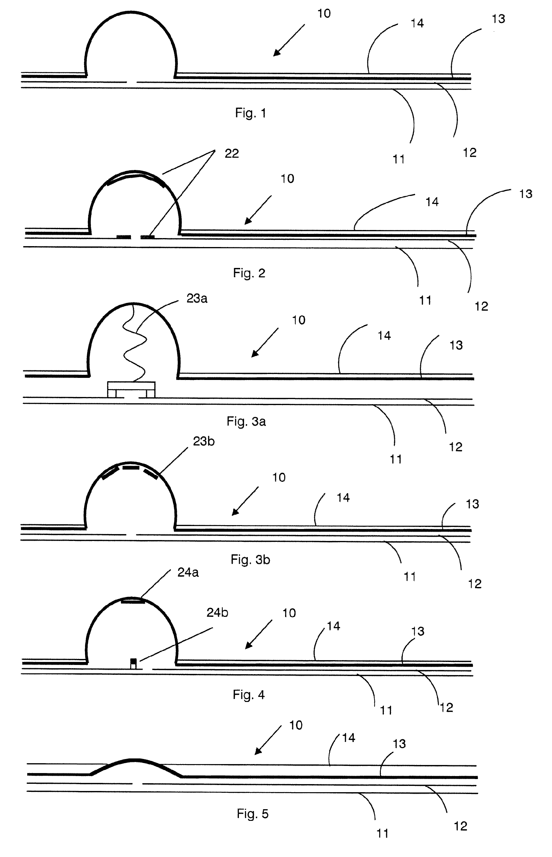
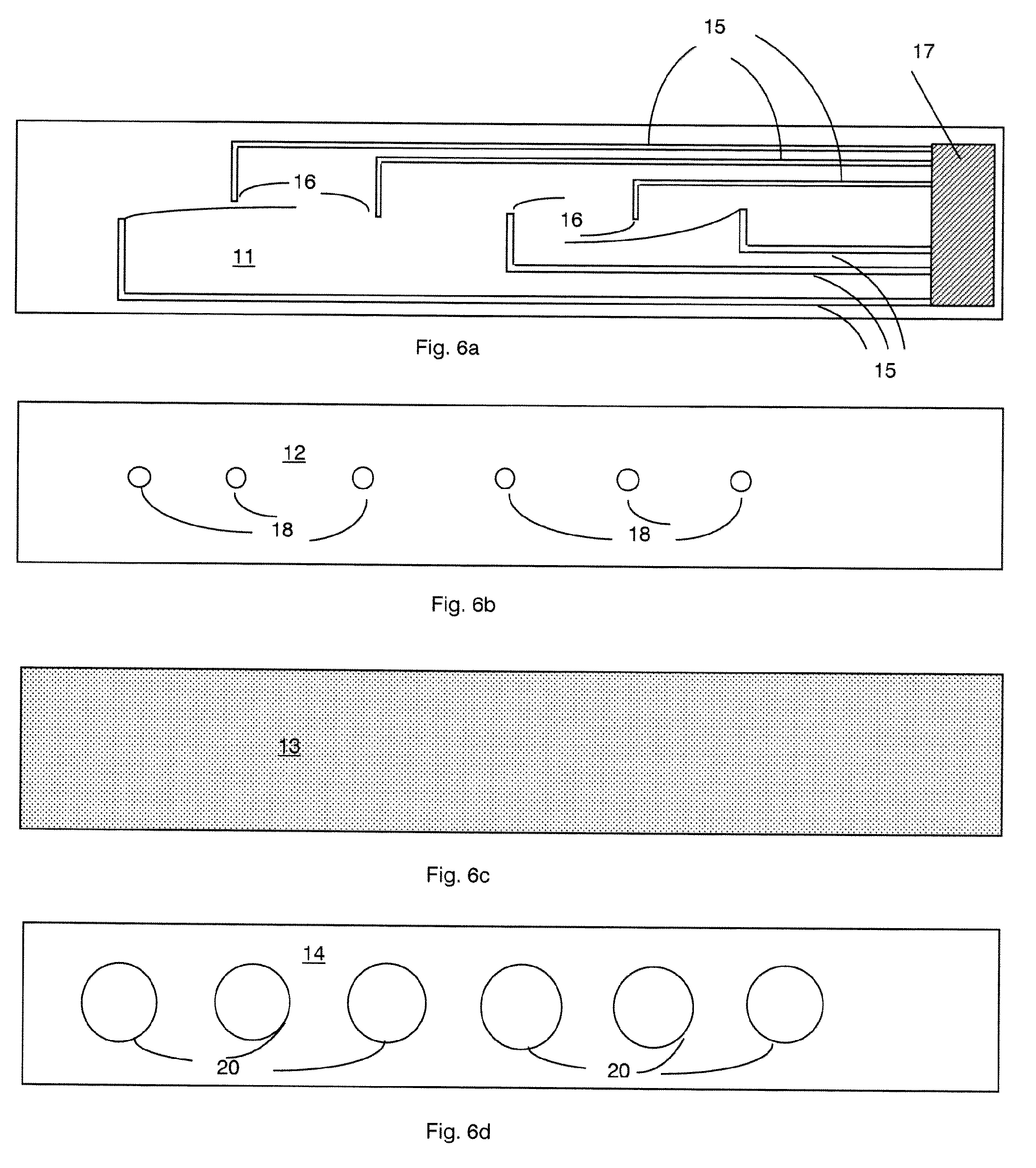
[0037]As shown in FIGS. 1 and 6, such a sensor may comprise a laminate of 4 layers, typically 3 of a plastic material and one of rubber. This provides a pneumatic ultra-thin (approx 2 mm), stable, pressure-sensing device. The construction is such that the two bottom layers form an airtight grooved multi-channel trunking. The third layer is the rubber layer and the top plastics layer has apertures through which the rubber can form an inflated dome. Although shown here as a circular dome this may also be elliptical or other shapes. The number and shape of the domes is not critical, but for this example a 6-dome structure is used. The plastics and rubber laminates are essentially oblong in shape, size and length are not limited, but in this example the width is 30 mm and the length 400 mm, with rounded end. The sensing domes are spaced along the length of the oblong section at suitable distances; the actual spacing is not limited, but in this example the spacing is appr...

example 2

Capacitative Sensor (FIG. 2)

[0047]The construction of a capacitive sensor is as for that of Example 1, with the addition of metal plates fixed to a recess in the top layer, and the inside of the dome is metal-coated. Connecting tracks are on the underside of the diaphragm material or in the grooved ducts. Connection to the electronics unit is via the connection block.

[0048]In operation, the diaphragm is inflated as per the pneumatic version. As the dome expands, the distance from the metal plates on the top layer and the metal on the inside of the dome changes, giving a change in capacitance value. The area of the metal inside the dome would also change, giving additional capacitance change. Once the capacitance value has stabilised (dome fully inflated), then any change in the dome shape would show a measurable change in capacitance. These changes will have a relationship to the pressure that is changing the dome's shape, and can be calibrated to give a linear relationship. On comp...

example 3

Strain Gauge Sensor (FIG. 3)

[0049]Construction of a strain gauge sensor is as for that of Example 2, but with a strain gauge fitted in place of the capacitor plates on the top layer and the centre of the dome attached to the centre of the stain gauge. Two possible versions of the strain gauge are shown in FIGS. 3a and 3b.

[0050]In operation, as the dome is inflated, the centre of the strain gauge is pulled up (3a), changing the strain gauge resistance. When the dome is fully inflated, applied external pressure on the dome will cause changes on the strain gauge proportional to the pressure applied.

[0051]An alternative is to coat the inside of the dome (3b) with a conductive element and this would then become the strain gauge. Again, any change with the inflated dome shape due to external pressure would cause changes to the conductive coating and therefore its resistance. This can then be calibrated to form a relationship between pressure and resistance.


PUM


Abstract

A sensor suitable for measuring the pressure applied by a bandage, the sensor being in the form of an elongate strip having a plurality of pads arranged along its length, wherein the sensor includes a connection to each pad, whereby the pressure applied to each pad can be determined independently, wherein each pad is inflatable to form an expanded pad protruding above the surface of the strip, and deflatable so that it does not impede removal of the sensor from the bandage. Such a sensor is primarily intended for single use, i.e. is disposable.

Description

CROSS REFERENCE TO A RELATED APPLICATION[0001]This application is a National Stage Application of International Application Number PCT / GB2012 / 050012, filed Jan. 5, 2012; which claims priority to Great Britain Application No. 1100096.5, filed Jan. 5, 2011; which are incorporated herein by reference in their entirety.FIELD OF THE INVENTION[0002]This invention relates to a sensor, and in particular to a device that can be used to measure pressure applied by a bandage or stocking around a leg ulcer.BACKGROUND OF THE INVENTION[0003]Venous leg ulcers affect between 1% and 1.5% of the UK population at any given time. Based on 60 million persons, this equates to approximately 200,000 with ulcers requiring treatment. Estimates of cost to treat range from £450 million to £800 million per year. In the USA, the estimate of cost to treat comes in at almost $5 billion per year. The average length of time any one person has an ulcer for is upwards of two years. If an ulcer does heal, relapse rates...

Claims


Application Information

Patent Timeline
Patent Type & Authority Patents(United States)
IPC IPC(8): A61B5/117A61B5/103A61B5/00A61F13/00
CPCA61B5/0053A61F13/00A61B2562/0247A61F2013/00957F04C2270/0421A61B5/103A61F2013/00902
Inventor DAVIES, ROY FREDERICKHUQ, EJAZBARKER, STEPHEN GEORGE EDWARD
Owner SFH OXFORD
Why Eureka
Try Eureka