Suspension spring mount

a technology for suspension springs and mounts, which is applied in the direction of springs/dampers, mechanical equipment, transportation and packaging, etc., can solve the problems of limiting the spring's ability to react to high compression loads, securing a composite spring within a suspension system, and presenting certain challenges

Inactive Publication Date: 2008-10-23
ARVINMERITOR TECH
View PDF9 Cites 35 Cited by
  • Summary
  • Abstract
  • Description
  • Claims
  • Application Information

AI Technical Summary

Problems solved by technology

Mounting composite springs within a suspension system presents certain challenges.
This method of securing a composite spring within a suspension system has disadvantages, especially under certain brake load applications.
Under this condition, composite springs experience a unique shear failure mode which limits the spring's ability to react to high compression loads from the windup bumper.
The use of the elastomer linings allows a certain degree of deflection within the bracket; however, as brake regulations become stricter, i.e. as required stopping distances become shorter, the shear failure mode becomes even more important.

Method used


Image

  • Suspension spring mount
  • Suspension spring mount
  • Suspension spring mount

Examples


Embodiment Construction

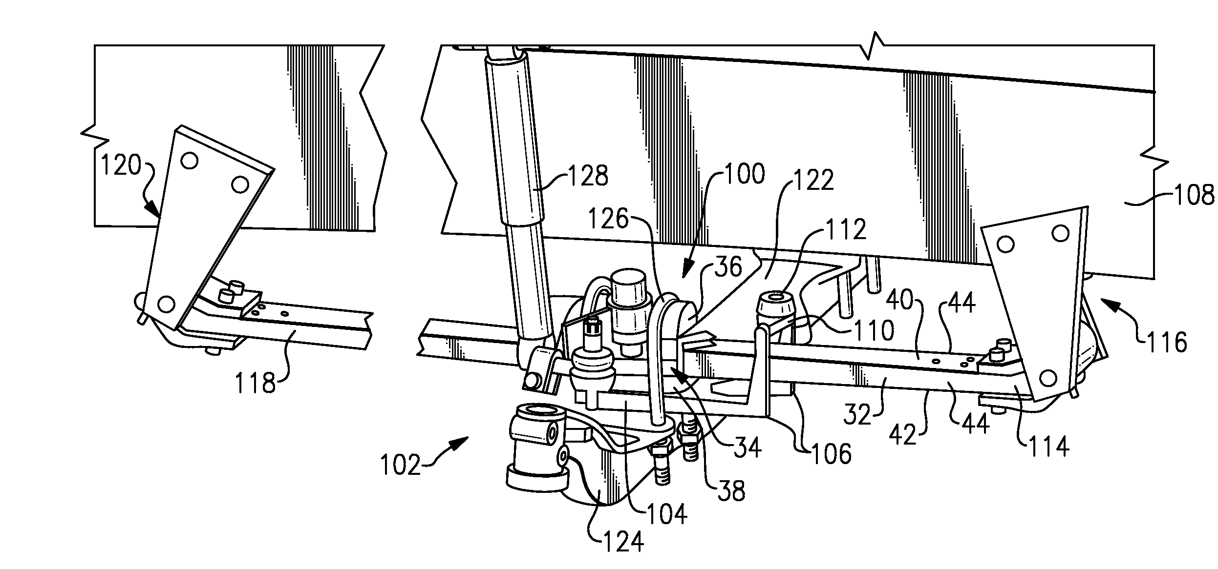
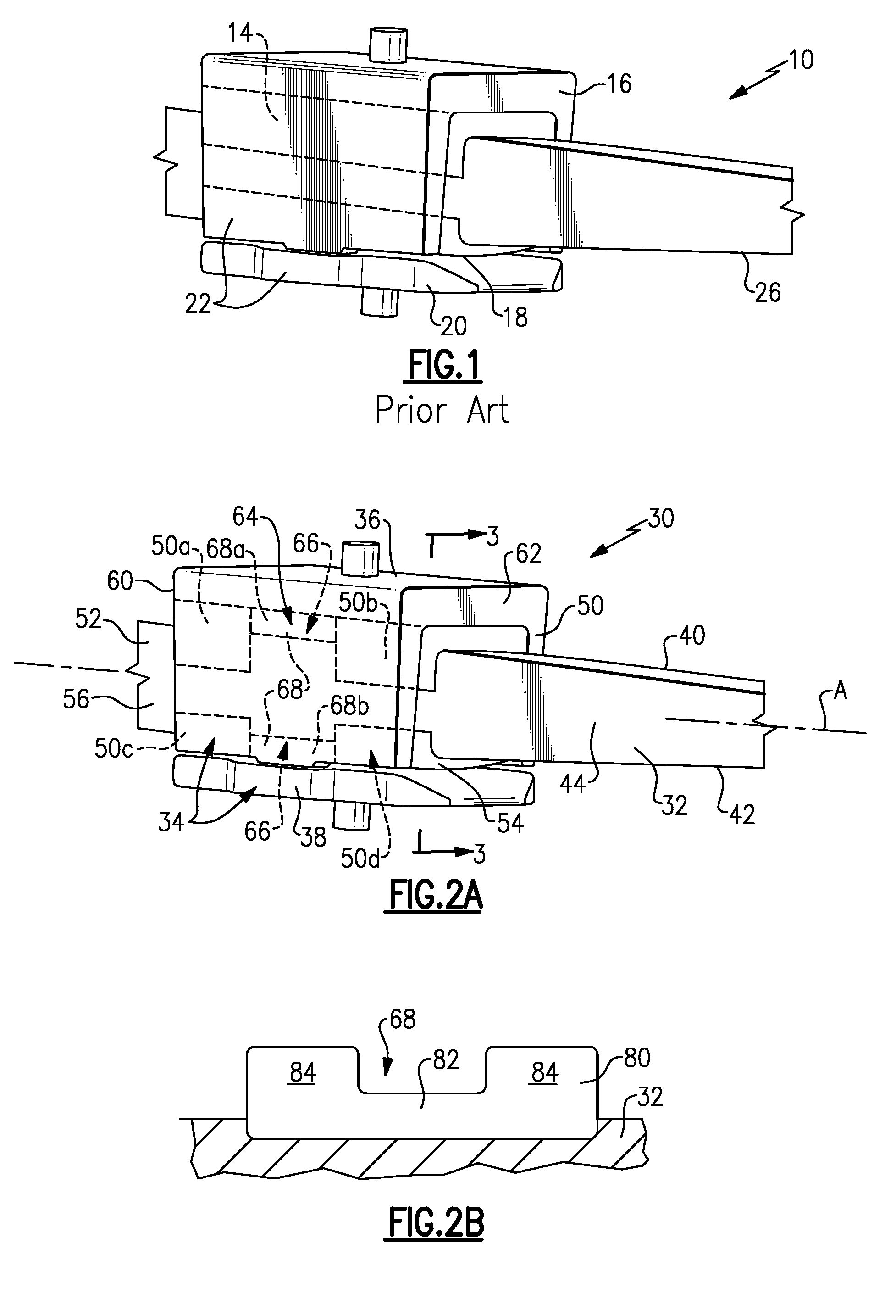
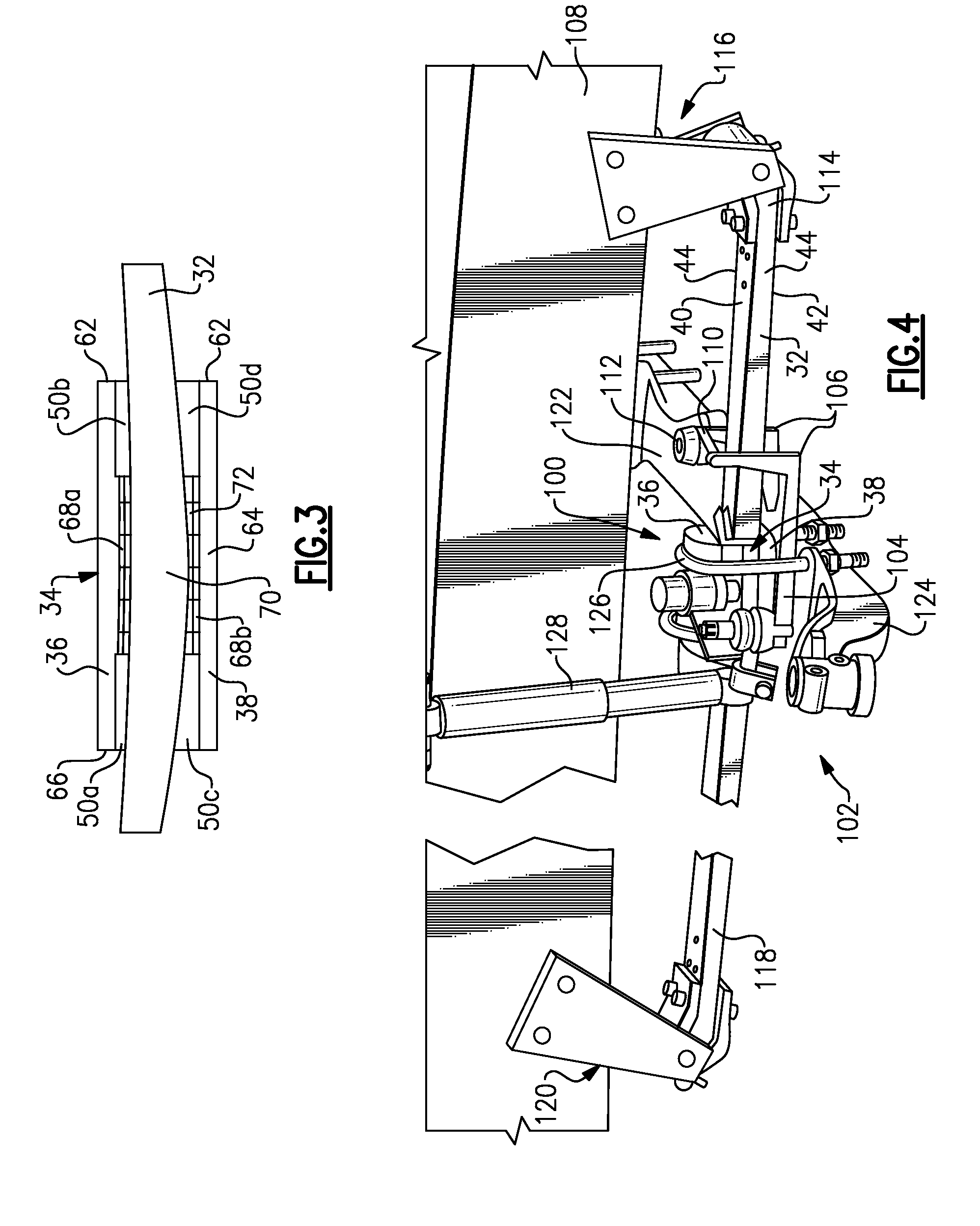
[0021]A spring mounting arrangement 30 according to one example includes a spring 32 housed within a housing assembly 34 as shown in FIG. 2A. The housing assembly 34 includes an upper housing portion 36 and a lower housing portion 38 that cooperate to surround the spring 32. Although shown as having similar lengths, the length of the upper housing portion 36 relative to the lower housing portion 38 may vary.

[0022]The spring 32 is shaped to have a rectangular cross-section and has an upper surface 40, a lower surface 42, and opposing lateral side edges 44. The spring 32 defines a longitudinal axis A that extends in a direction corresponding to a longitudinal length of a vehicle. The upper housing portion 36 is C-shaped such that the upper housing portion 36 surrounds the upper surface 40 and opposing lateral side edges 44. The lower housing portion 38 surrounds or covers the lower surface 42. The upper 36 and lower 38 housing portions cooperate to completely surround a central portio...


PUM


Abstract

A spring is to be supported on an axle with a housing. The housing surrounds a portion of the spring and has a housing inner portion positioned between first and second housing end portions. A lining secures the spring to the housing. A portion of the lining at the first and second housing end portions is thicker than a portion of the lining at the housing inner portion.

Description

RELATED APPLICATIONS[0001]This application claims priority to U.S. Provisional Application No. 60 / 912,504 filed on Apr. 18, 2007.TECHNICAL FIELD[0002]This invention generally relates to mounting a spring within a suspension system, and more specifically relates to a housing and spring mount assembly for a vehicle suspension.BACKGROUND OF THE INVENTION[0003]Suspension systems use springs to provide desired ride control characteristics. In one known configuration, the springs extend in a longitudinal direction along a length of a vehicle and include one end that is connected to a vehicle frame or chassis member, a center portion that is supported on an axle, and an opposite end that is connected to the vehicle frame or chassis member. As known, the springs move and flex in response to road load and braking load inputs.[0004]Spring mounts are used to secure the springs to the axle to permit movement of the spring between biased and unbiased positions. The springs can be made from diffe...

Claims


Application Information

Patent Timeline
Patent Type & Authority Applications(United States)
IPC IPC(8): B60G11/00
CPCB60G9/003B60G11/44B60G11/46B60G11/62B60G11/64B60G2200/314B60G2202/112B60G2202/152B60G2204/4306
Inventor WEN, XINYUSOMNAY, RAJESHVARELA, TOMAZ DOPICOTROTTER, JAMES
Owner ARVINMERITOR TECH
Why Eureka
Try Eureka