Lighting device for vehicle and door mirror device

a technology for vehicle mirrors and light fittings, applied in the field of lighting, can solve the problems of poor degree of design freedom, inconvenient reduction of decorating characteristics, lack of flexibility in design, etc., and achieve the effect of improving a decorating function

Inactive Publication Date: 2008-10-23
ICHIKOH IND LTD
View PDF18 Cites 3 Cited by
  • Summary
  • Abstract
  • Description
  • Claims
  • Application Information

AI Technical Summary

Benefits of technology

[0017]An object of the present invention is to provide a lighting device which is capable of flexibly being adjusted to regulations of each area having a different range of a light distribution angle and capable of improving a decorating function by making light-emitting diodes become difficult to visually contact from outside, and a door mirror device using the lighting device.

Problems solved by technology

Incidentally, in this type of the lighting device for vehicle where the inside is seen from outside, since the inside of the lighting device for vehicle is seen through the outer lens even when the light-emitting diodes are not turned ON, there is an inconvenience that a decorating characteristic reduces.
For this reason, the lighting device for vehicle having the reflector has an inconvenience that the degree of freedom in design is poor and lacks flexibility in design.
Furthermore, in this type of lighting device for vehicle in which the inside is seen through the outer lens also has an inconvenience that a decorating characteristic reduces since the light-emitting diodes are seen from outside through the outer lens.

Method used


Image

  • Lighting device for vehicle and door mirror device
  • Lighting device for vehicle and door mirror device
  • Lighting device for vehicle and door mirror device

Examples


example 1

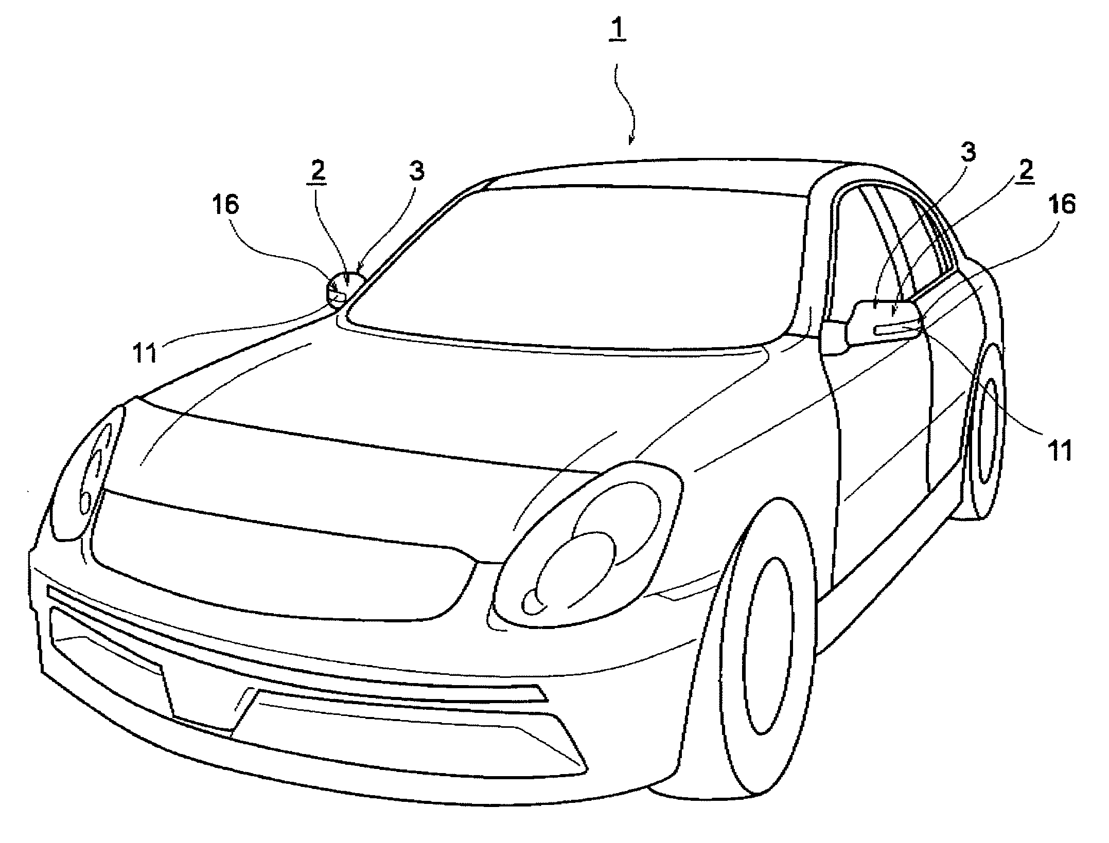
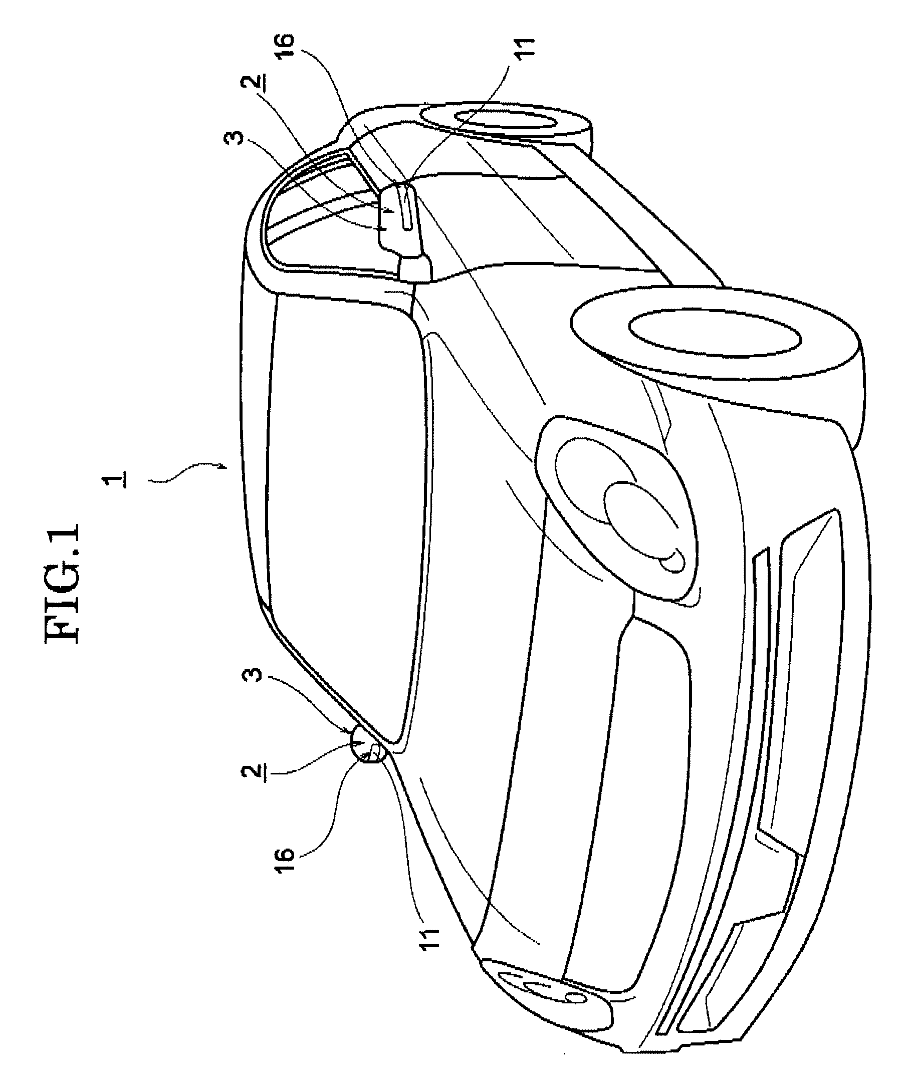
[0031]A lighting device according to an embodiment of the present invention may be used in a door mirror device (door mirror) as an outer mirror. FIG. 1 is the perspective view showing a state where door mirror devices as outer mirrors for vehicle, each of which is provided with a lighting device for vehicle according to an embodiment of the present inventions are erected to a vehicle body.

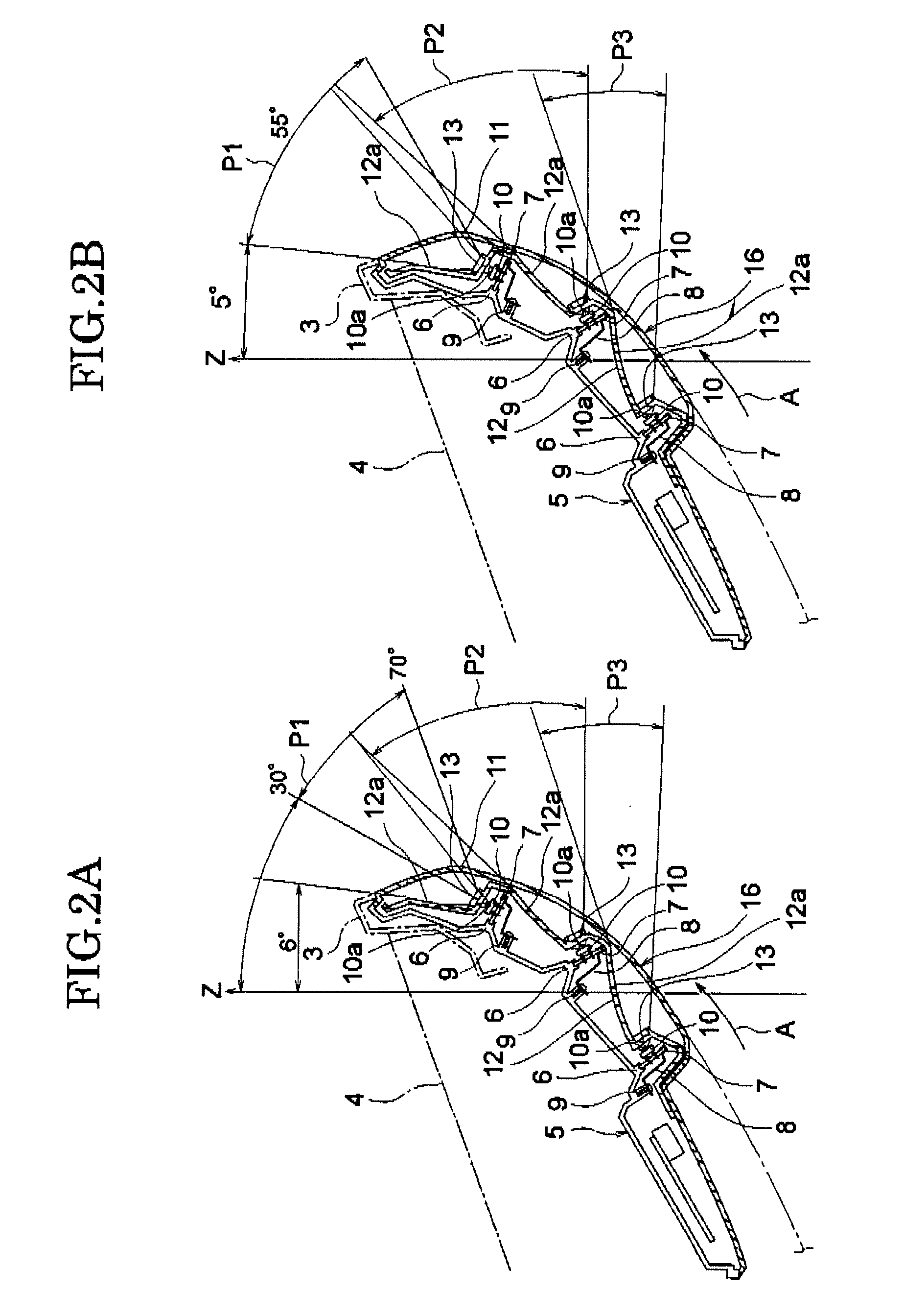
[0032]In FIG. 1, reference numeral 1 denotes a vehicle body, and 2 denotes a door mirror as an outer mirror for vehicle. The door mirror 2 has a lighting device including a housing body 3 which is configured to hold the door mirror 2 for rear viewing as shown in FIG. 2 in an enlarged manner. The door mirror 2 is designed to be turnable between an erected state and a retracted state to the vehicle body 1.

[0033]The housing body 3 has a shape curved backwardly (arrow A direction) from an inner end portion toward an outer end portion in a width direction of the vehicle body 1 at a rear surface side of...

example 2

[0051]In the above Example 1, the configuration for manufacturing the lighting device for vehicle 16 capable of flexibly being adjusted to regulations of each area having a different range of the light distribution angle by forming the transparent flat plate or the prism surface on the light transmitting portions 13 of the decorating wall 12, is employed. The lighting device for vehicle is also capable of improving the decorating function by making light-emitting diodes become difficult to visually contact from outside. However, a configuration having the shape described below can be also employed as the decorating wall.

[0052]Herein, the decorating wall 12 has openings 17 as the light transmitting portions 13 and positioning protrusions 18 as shown in FIG. 4A. A mold die to form the openings 17 (not shown) and a mold die to form the positioning protrusions 18 (not shown) are provided on a cavity to form the decorating wall 12. Consequently, the molded component of the decorating wal...


PUM


Abstract

A lighting device for vehicle include a housing body, an outer lens provided on the housing body, a decorating wall provided between the housing body and the outer lens and a plurality of light emitting devices which are provided between the housing body and the decorating wall and disposed with intervals to each other. The decorating wall includes a plurality of light transmitting portions, each of which is disposed to face each of the plurality of light emitting devices. The light transmitting portion is disposed to set light emitted from the corresponding light emitting device within a range of a predetermined light distribution angle.

Description

CROSS-REFERENCE TO THE RELATED APPLICATIONS[0001]The present application is based on and claims priority from Japanese Application Number 2006-298598, filed on Nov. 2, 2006, the disclosure of which is hereby incorporated by reference herein in its entirety.BACKGROUND OF THE INVENTION[0002]1. Field of the Invention[0003]The present invention relates to a lighting device for vehicle used in an outer mirror for vehicle, particularly to a lighting device for vehicle preferably used in a door mirror device.[0004]2. Description of Related Art[0005]Conventionally, there is known a lighting device for vehicle provided on a housing body which constitutes a part of a door mirror device as an outer mirror. In the lighting device, a plurality of light-emitting diodes (LED) as light emitting devices are provided on an outer end portion of the housing body in a width direction of a vehicle (vehicle width direction) and disposed with intervals in a horizontal direction. The lighting device for veh...

Claims


Application Information

Patent Timeline
Patent Type & Authority Applications(United States)
IPC IPC(8): B60Q1/26F21W107/10
CPCB60Q1/2665B60Q1/2696B60R1/1207B60Q1/32B60R1/06
Inventor YAJIMA, YASUOOKADA, SATORU
Owner ICHIKOH IND LTD
Why Eureka
Try Eureka