Optical Security Sensors, Systems, and Methods

a technology of optical security sensors and optical sensors, applied in the field of optical security sensors, systems and methods, can solve problems such as noise, false alarms are problematic, and the alignment of transmitters, receivers, reflectors can be compromised

Inactive Publication Date: 2008-10-30
THE COLONIE GROUP
View PDF14 Cites 9 Cited by
  • Summary
  • Abstract
  • Description
  • Claims
  • Application Information

AI Technical Summary

Benefits of technology

[0008]The present invention provides in a first aspect, a sensor for use with at least one optical fiber for a fence security system. The sensor includes a plate for attaching the sensor to the fence, a striker movably attached to the plate and the striker comprising a weight. The sensor is configured for receiving the at least one optical fiber between the striker and the plate. The striker is movable in response to vibration of the fence towards and away from the plate to compress the at least one optical fiber between the striker and the plate to bend the at least one optical fiber and attenuate transmission of an optical signal through the at least one optical fiber.

Problems solved by technology

A disadvantage of these systems is that they are very sensitive to noise, especially wind, and false alarms are problematic.
Additionally, since multimode fibers will only transmit light over relatively short distances, this demands placing the system electronics near the perimeter fence.
A disadvantage of these systems is that the sensitive alignment of transmitters, receivers, and reflectors can be compromised by wind and ground vibrations or by the wear of fixtures under the constant force of the earth's gravity.

Method used


Image

  • Optical Security Sensors, Systems, and Methods
  • Optical Security Sensors, Systems, and Methods
  • Optical Security Sensors, Systems, and Methods

Examples


Embodiment Construction

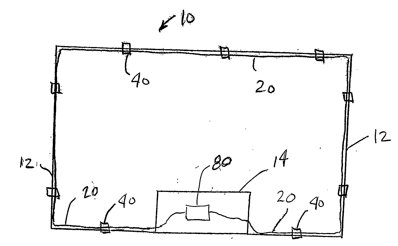
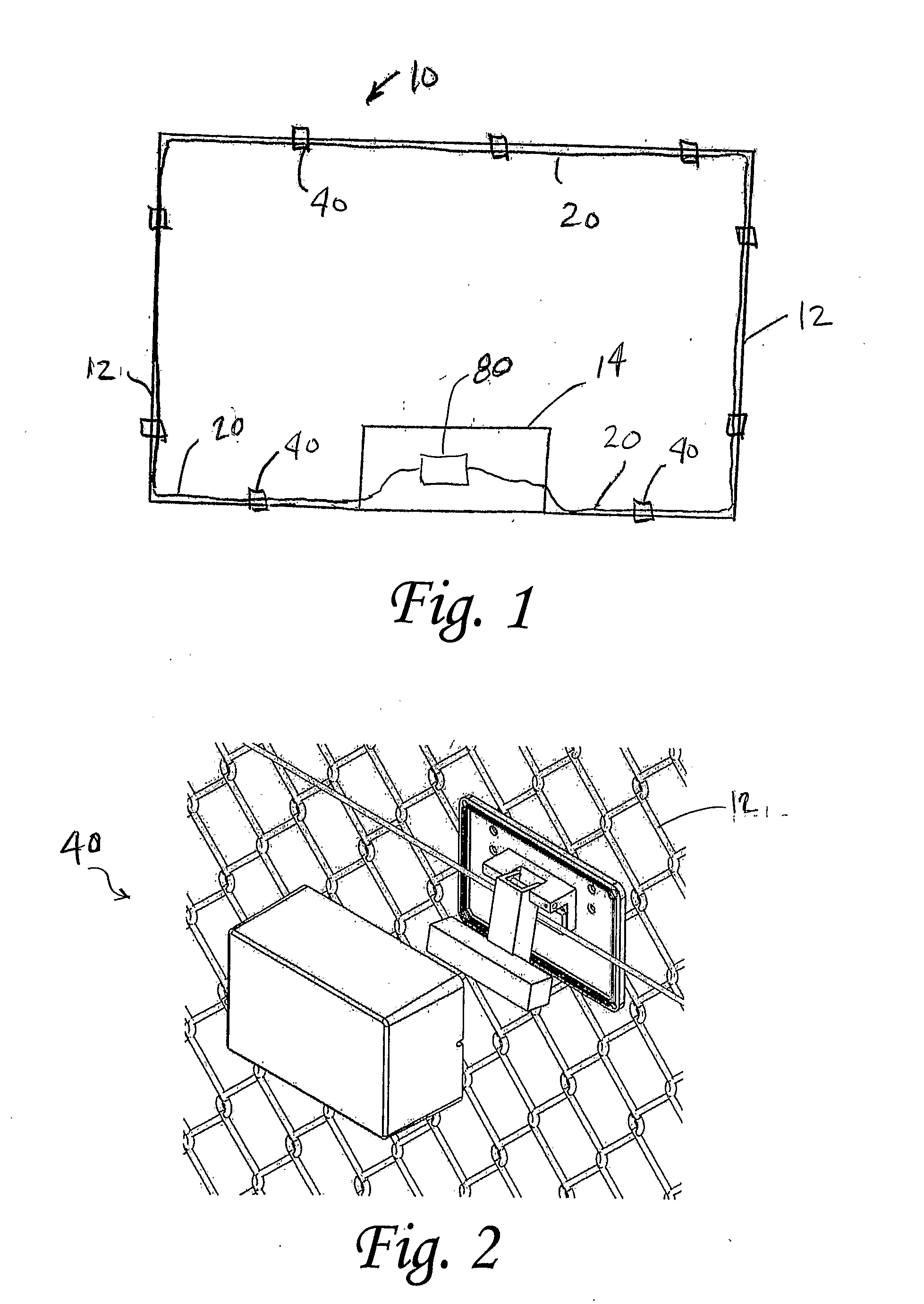
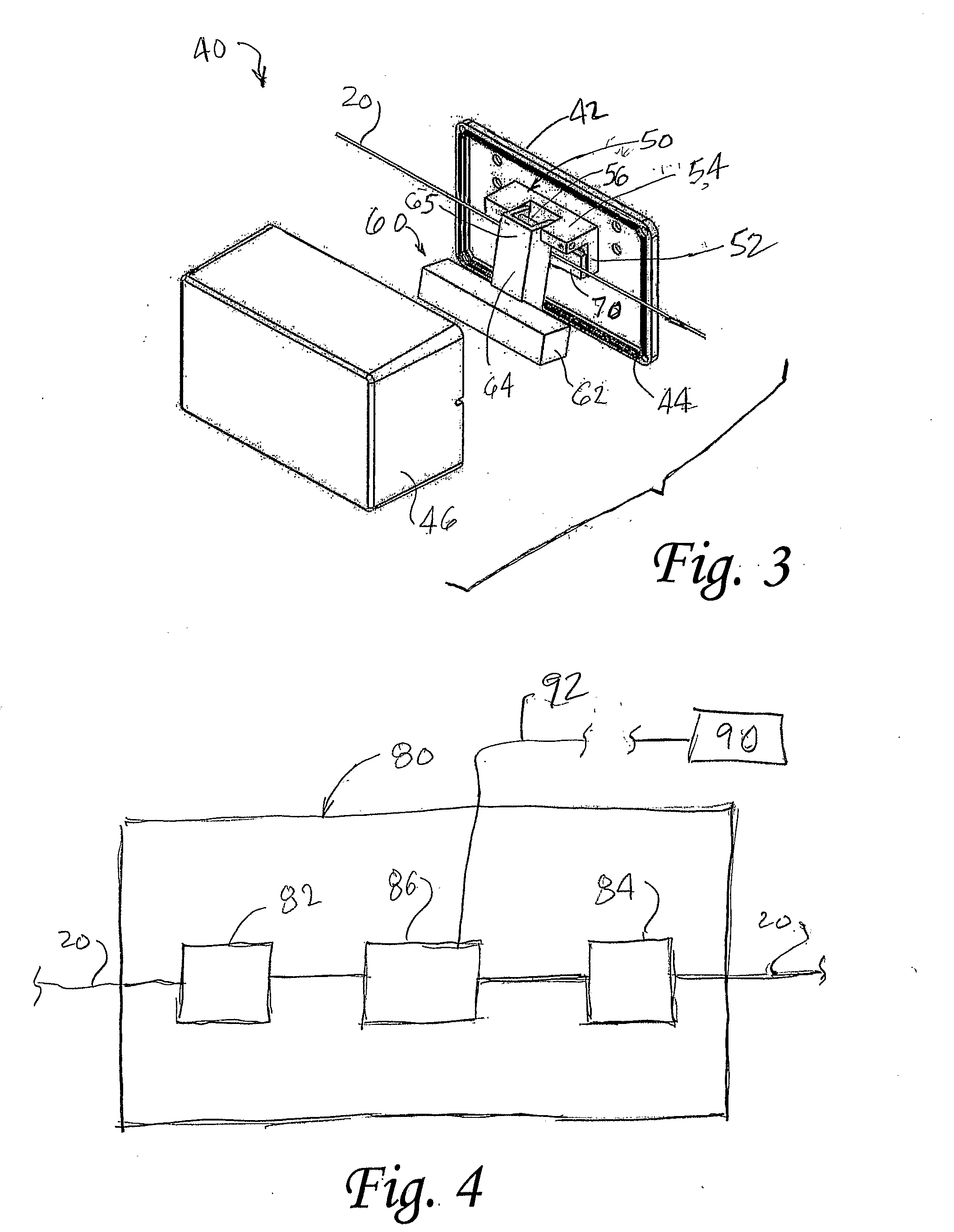
[0028]The present invention is directed to improving the security of perimeter fences by monitoring fence vibrations using a series of fiber optic sensors installed on the fence and / or monitoring motion via ground sensors positioned on the ground, and optoelectronic circuitry that may interface with other security systems. The sensors for the fence may employ a striker having a weight which swings under the influence of gravity and which is movable in response to vibration of the fence to compress and / or bend an optical fiber to attenuate transmission of an optical signal (cause optical loss) through the optical fiber. In one embodiment, the sensors may be installed on the perimeter fence and monitored using a single optical fiber. In another embodiment, the sensors may be installed on the perimeter fence and monitored via an optical fiber cable having a plurality of optical fibers, thereby enabling the sensors to be collected into zones for detection of the alarm position. A furthe...


PUM


Abstract

A security system includes an optical fiber, a plurality of sensors, and a light source, detector, and a controller. The optical fiber and sensors are attached and positioned along a fence. The optical fiber passes through the sensors. The sensors include a hinged striker having a weight that swings under the influence of gravity and is movable in response to vibration of the fence to compress and bend the optical fiber and attenuate transmission of an optical signal through the optical fiber. In another embodiment, an optical fiber cable having a plurality of optical fibers may be employed to define zones and allow determination of intrusion of a particular portion of the fence. In a further embodiment, a ground sensor is disclosed.

Description

CROSS-REFERENCE TO RELATED APPLICATION[0001]This application claims the benefit of U.S. Provisional Application No. 60 / 651,191, filed Feb. 9, 2005, entitled “Fiber Optic Fence Security Sensor and System,” the entire subject matter of these applications being incorporated herein by reference.FIELD OF THE INVENTION[0002]The present invention relates to security systems and, more specifically, to optical security sensors, systems, and methods.BACKGROUND OF THE INVENTION[0003]With the greater awareness of security threats, there is an increasing need for security systems that sense potential intrusions, analyze the sensor signals to evaluate the likelihood of attack, and communicate with a centralized security system. Perimeter fencing offers protection by being a barrier to intrusion.[0004]Historically fence security systems have been comprised of taut wires connected to sensors that detect changes in tension. These systems typically have thresholds that the tension sensors need to exc...

Claims


Application Information

Patent Timeline
Patent Type & Authority Applications(United States)
IPC IPC(8): G08B13/18
CPCG08B13/124G08B13/186
Inventor TATAR, ROBERT C.STEWART, KEVIN R.
Owner THE COLONIE GROUP
Why Eureka
Try Eureka