Method and tool for creating a passive shim location within a gradient coil

Inactive Publication Date: 2008-11-06
GENERAL ELECTRIC CO
View PDF3 Cites 4 Cited by
  • Summary
  • Abstract
  • Description
  • Claims
  • Application Information

AI Technical Summary

Problems solved by technology

Inhomogeneities in the magnetic field, B0, can adversely affect data acquisition and reconstruction of an MR image.

Method used


Image

  • Method and tool for creating a passive shim location within a gradient coil
  • Method and tool for creating a passive shim location within a gradient coil
  • Method and tool for creating a passive shim location within a gradient coil

Examples


Embodiment Construction

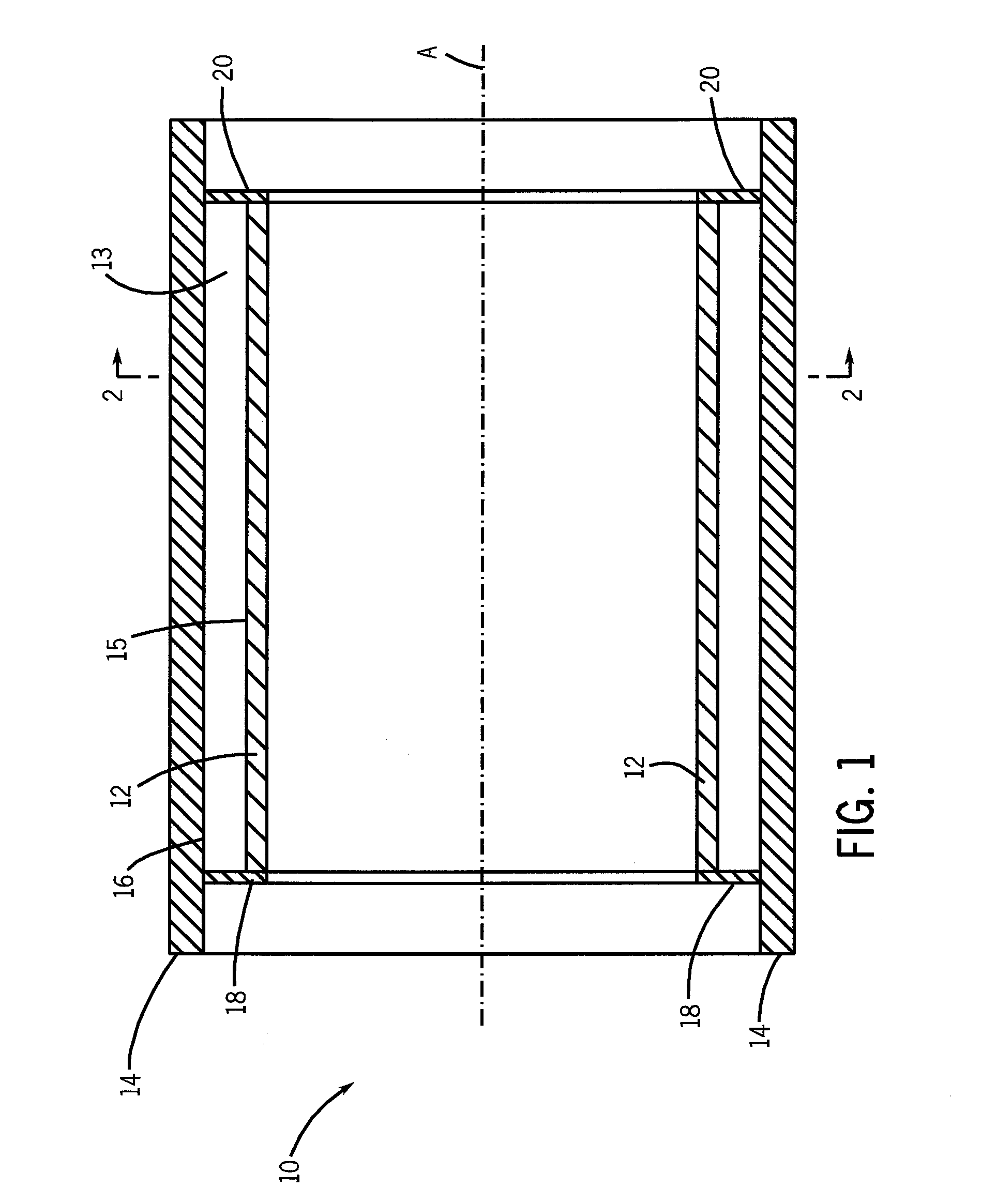
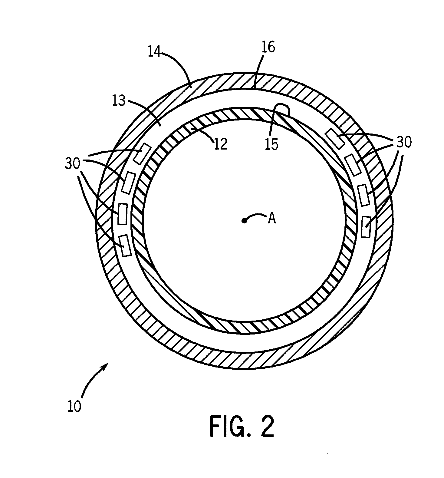
[0015]FIGS. 1 and 2 show a self-shielded gradient coil assembly 10 for an MR imaging system (not shown). FIG. 1 is a sectional view, taken in a plane through a central longitudinal axis, of a MR gradient coil assembly and FIG. 2 is a cross-sectional view taken along line 2-2 of the MR gradient coil assembly of FIG. 1. In FIGS. 1 and 2, the gradient coil assembly 10 comprises a cylindrical inner gradient coil assembly or winding 12 and a cylindrical outer gradient coil assembly or winding 14 disposed in concentric arrangement with respect to a common axis A. Inner gradient coil assembly 12 includes inner coils of X-, Y-, and Z-gradient coil pairs, or sets, and outer gradient coil assembly 14 includes the respective outer coils of the X-, Y- and Z-gradient coils pairs or sets. Gradient coil assembly 10 shown in FIGS. 1 and 2 may be inserted into the bore of a main magnet (not shown) of an MRI system so that axis A aligns with the bore axis of the main magnet (not shown). The coils of ...


PUM

PropertyMeasurementUnit
Volumeaaaaaaaaaa
Flexibilityaaaaaaaaaa
Dimensionaaaaaaaaaa

Abstract

A method for creating a passive shim location in a gradient coil assembly of a magnetic resonance imaging system includes placing at least one tool in a volume between an inner gradient coil assembly and an outer gradient coil assembly. The tool includes an inner core and an outer sleeve. The inner core is removably housed in the outer sleeve. The volume is then filled with a bonding material. Once the bonding material has cured, the inner core is removed from the outer sleeve. The outer sleeve may also be removed from the volume.

Description

FIELD OF THE INVENTION[0001]The present invention relates generally to magnetic resonance imaging (MRI) systems and in particular to a method and tool for creating a passive shim location within a gradient coil of a MRI system.BACKGROUND OF THE INVENTION[0002]Magnetic resonance imaging (MRI) is a medical imaging modality that can create images of the inside of a human body without using x-rays or other ionizing radiation. MRI uses a powerful magnet to create a strong, uniform, static magnetic field (i.e., the “main magnetic field”). When a human body, or part of a human body, is placed in the main magnetic field, the nuclear spins that are associated with the hydrogen nuclei in tissue water become polarized. This means that the magnetic moments that are associated with these spins become preferentially aligned along the direction of the main magnetic field, resulting in a small net tissue magnetization along that axis (the “z axis,” by convention). An MRI system also comprises compo...

Claims


Application Information

Patent Timeline
IPC IPC(8): B29C47/00
CPCG01R33/385G01R33/3856Y10T156/1744G01R33/4215G01R33/3873
Inventor CLARKE, NEILCROUCHEN, JOHN MARKMCKENDRY, ALAN
Owner GENERAL ELECTRIC CO
Why Eureka
Try Eureka