Spray Gun

Inactive Publication Date: 2008-11-06
HYPHONE MASCH IND CO LTD
View PDF7 Cites 55 Cited by
  • Summary
  • Abstract
  • Description
  • Claims
  • Application Information

AI Technical Summary

Benefits of technology

[0007]It is an objective of the present invention to provide an apparatus which has a simple construction.
[0008]It i

Problems solved by technology

Anyway, the spray gun 94 has only one spraying angle

Method used


Image

  • Spray Gun
  • Spray Gun
  • Spray Gun

Examples


Embodiment Construction

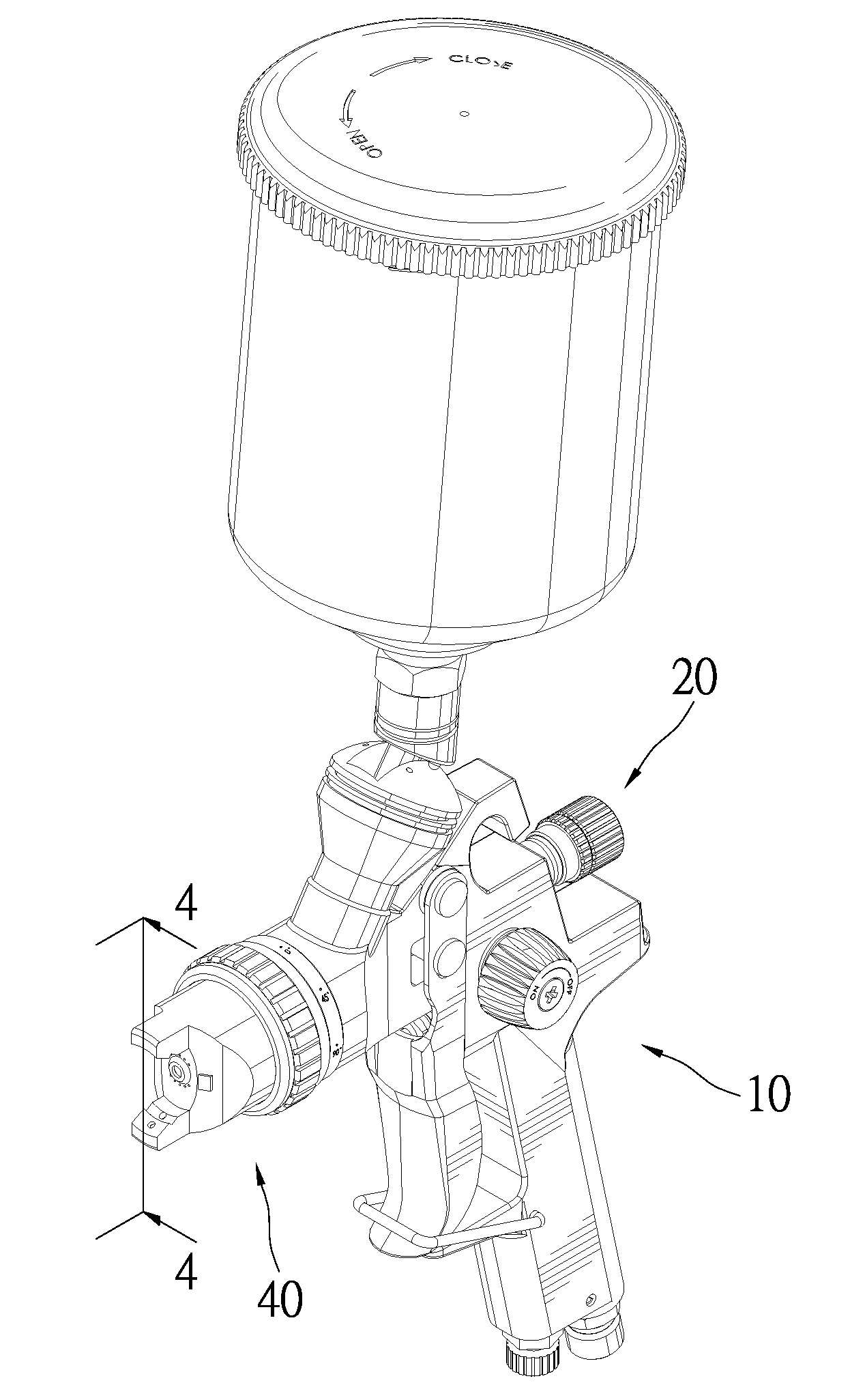
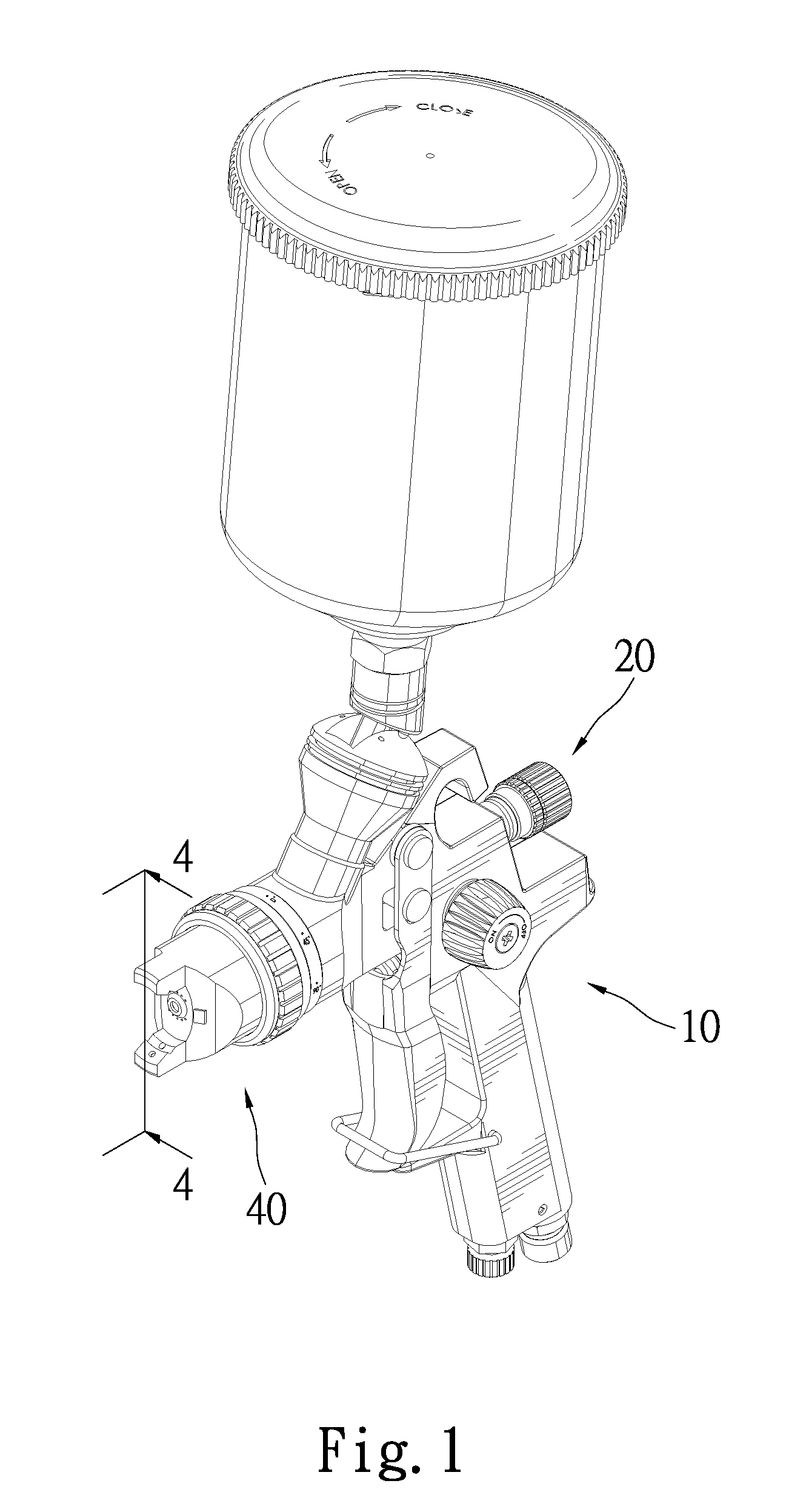
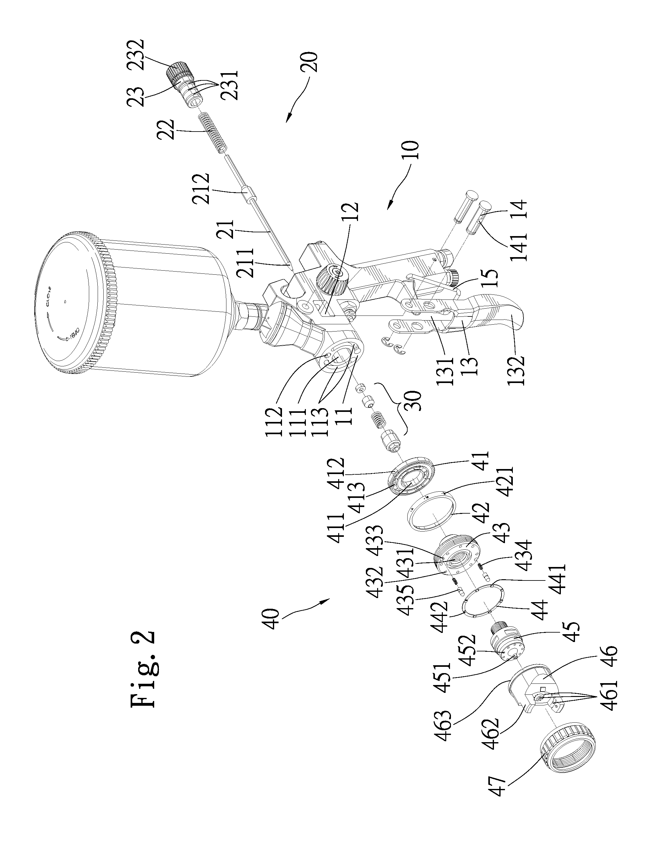
[0024]FIGS. 1 through 3 illustrate a spray gun according to the present invention includes a body 10, a control device 20 which is adapted to control the flow rate of liquid, a valve 30, and a nozzle portion 40 which connects to the body 10 and define an interface 11 therebetween. The control device 20 is disposed on one side of the interface 11 while the valve 30 and the nozzle portion are disposed on the opposite side thereof. The body 10 includes a hole 111, a cavity 112 and two air-inlet passages 113 extending from the interface 11 in an axial direction. The cavity 112 is defined above the hole 111. The air-inlet passages 113 are defined around the hole 111. The hole 111 is adapted to provide a passage way for the liquid.

[0025]The body 10 also includes a through-hole 12 disposed in a direction perpendicular to the hole 111, with the through-hole 12 intersecting the hole 111 at about the mid-region thereof. The through-hole 12 is adapted to receive a pivotal portion 131 defined o...


PUM


Abstract

A spray gun includes a body, a hole defined thereof, and a nozzle portion. The nozzle portion includes an air-inducting device communicating with the hole, with the air-inducting device including a bore for allowing liquid to flow through and a plurality of retaining sections. Each retaining section includes an elastic element and a detent disposed therein. The nozzle portion also includes a positioning ring having a plurality of engaging portions disposed on an end and an air cap including two horns and a plurality of outlet holes adapted for allowing liquid to flow out. The engaging portions are adapted for receiving the detent. The air cap includes two horns and a plurality of outlet holes adapted for allowing liquid to flow out, with the air cap engaging with the positioning ring.

Description

BACKGROUND OF THE INVENTION[0001]1. Field of the Invention[0002]The present invention relates to a spray gun, in particular, to a spray gun of which spraying angle can be adjusted.[0003]2. Description of the Related Art[0004]FIG. 13 illustrates a conventional spray gun 94 comprising a head portion 91, horns 92 and a cap 93. The head portion 91 includes a nozzle head 912 with an outlet end 913 which allows liquid to be sprayed from the spray gun 94 to the outside environment. The head portion 91 also has a male thread portion 911 defined on the periphery for attachment to the cap 93. The conventional spray gun 94 can directs air under controlled flow rate and pressure against liquid flowing out of the outlet end 93 so as to achieve a symmetrical and foggy painting effect. Anyway, the spray gun 94 has only one spraying angle and the control of amount of liquid is not enabled.[0005]The present invention is, therefore, intended to obviate or at least alleviate the problems encountered i...

Claims


Application Information

Patent Timeline
IPC IPC(8): B05B1/34
CPCB05B7/0815B05B7/2435
Inventor TING, CHIN-MING
Owner HYPHONE MASCH IND CO LTD
Why Eureka
Try Eureka