Method and Apparatus for Measuring a Parameter within the Well with a Plug

Inactive Publication Date: 2008-11-06
SCHLUMBERGER TECH CORP
View PDF15 Cites 99 Cited by
  • Summary
  • Abstract
  • Description
  • Claims
  • Application Information

AI Technical Summary

Benefits of technology

[0012]Preferably, the sensor is a miniaturized sensor self supplied in power. The associated electronics are small and with low consummation: a sensor with limited volume and limited power supply allow a minimum bulk. For example, sensors can be of the type MEMS. Most preferably, the sensor is auto-sufficient in terms of power supply. For example, sensors can be of the type optical sensor even embodied within the optic fiber line; when an optical signal is sent to the optical sensor, the signal reflected by said sensor informed on the measured physical parameter. For example, the sensor is a temperature sensor and/or a pressure sensor in the family of Bragg grating sensor. More preferably, the syst

Problems solved by technology

At the current time this can not be done as there is no robust telemetry method that is practical with conventional operating practices.
The problem is that the cementing plug can not be deployed for long distances and measurements are limited only to measured value on the plug, so insid

Method used


Image

  • Method and Apparatus for Measuring a Parameter within the Well with a Plug
  • Method and Apparatus for Measuring a Parameter within the Well with a Plug
  • Method and Apparatus for Measuring a Parameter within the Well with a Plug

Examples


Example

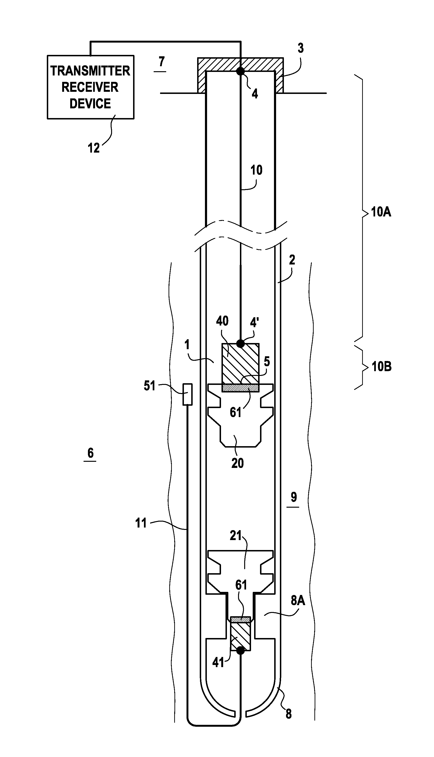
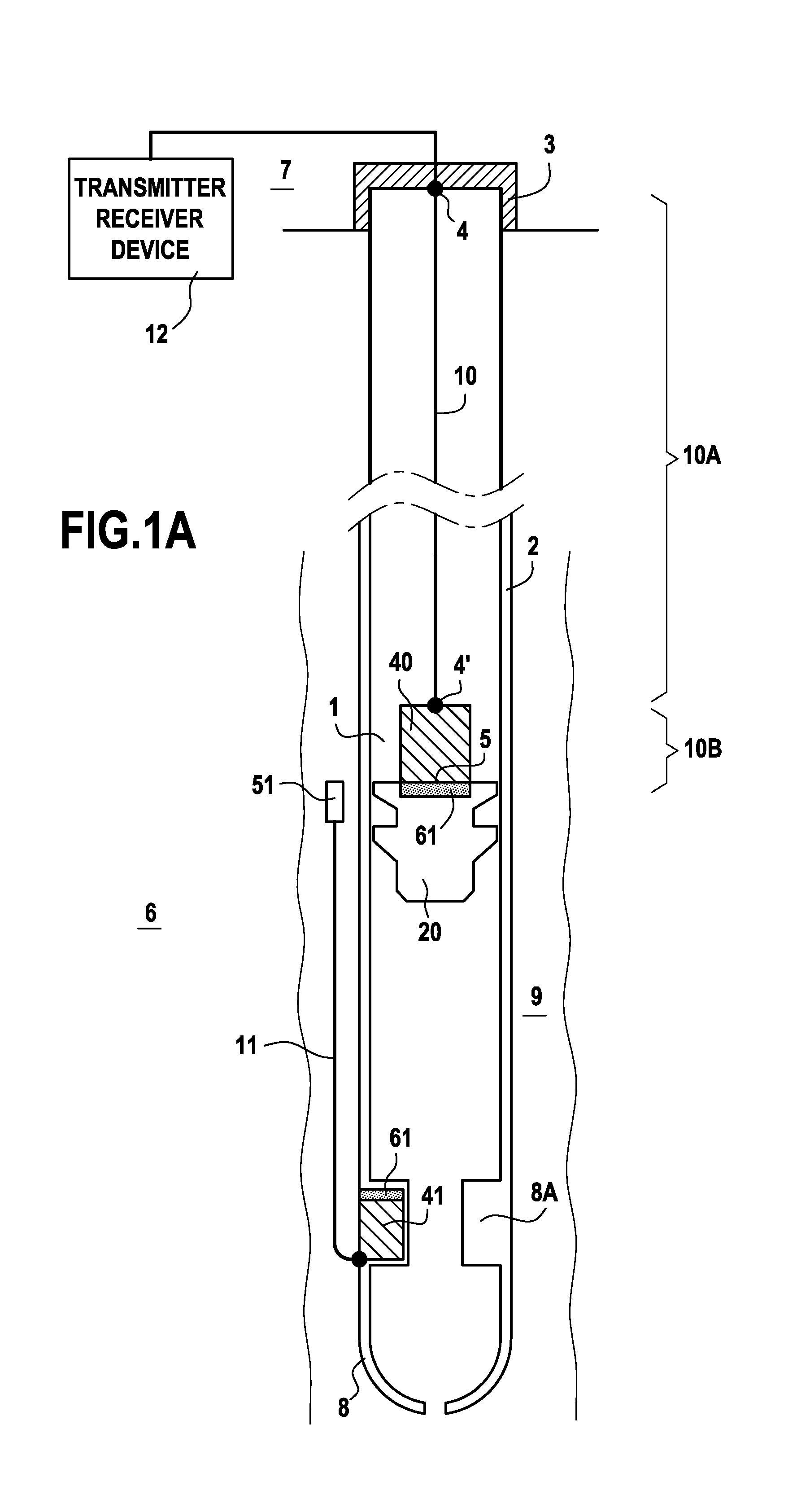
[0027]FIG. 1A is a view of the system in a first embodiment deployed in a cased wellbore 1 within a formation 6. The wellbore is made of a casing 2 with a guide shoe 8. The guide shoe 8 comprises a landing collar 8A with float valve. The casing forms an annulus 9 between the casing 2 and the formation 6. The system according to the invention is made of a first apparatus embodied here as the guide shoe 8, which comprises a first reel 41 of a first wound optic fiber line 11. The first reel 41 is located here within the landing collar 8A. Further, the first optic fiber line 11 is able to be unwound from the first reel 41. The first optic fiber 11 unwinds directly in the annulus 9 as shown on FIG. 1A. However by way of others embodiments, the first reel 41 can be located elsewhere; the first optic fiber 11 can be deployed inside the casing 2 and can also go through the guide shoe 8 into the annulus 9. The first apparatus comprises also at least a first sensor 51 able to measure a parame...

Example

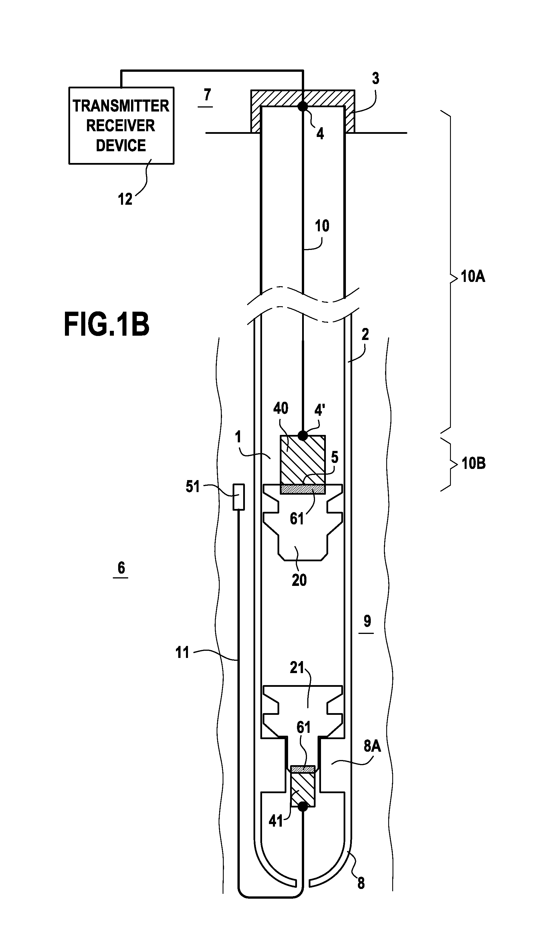
[0032]FIG. 1B is a view of the system in a second embodiment deployed in the cased wellbore 1 within the formation 6. The system according to the invention is made of a first apparatus embodied here as a plug 21, which comprises a first reel 41 of a first wound optic fiber line 11. The first reel 41 is located here at the bottom of the plug 21. Further, the first optic fiber line 11 is able to be unwound from the first reel 41. The first optic fiber 11 unwinds by passing through the guide and directly in the annulus 9 as shown on FIG. 1B. However by way of others embodiments, the first reel 41 can be located elsewhere, for example the plug can comprise a hole traversing entirely the plug, the first reel being located inside this one. Also by way of others embodiments, the first optic fiber 11 can be deployed inside the casing 2 and can also go through the guide shoe 8 into the annulus 9. The other characteristics of the system are the same as for the embodiment as disclosed on FIG. ...


PUM


Abstract

The invention provides a system for measuring a parameter within a well comprising: a first apparatus comprising a first reel of first wound optic fiber line (or fiber) able to be unwound from the first reel, at least a first sensor able to measure the parameter of the well, wherein information on said parameter can be transmitted trough the first optic fiber; a second apparatus comprising a second reel of second wound optic fiber line able to be unwound from the second reel, an extremity of the second optic fiber being fixed to a reference point; a light transmitter or receiver device linked to the reference point and able to generate or detect a light pulse through the second optic fiber line; and means to exchange said light pulse between first and second optic fiber line.

Description

FIELD OF THE INVENTION[0001]The present invention generally relates to apparatus and methods for completing a well. Particularly, the present invention relates to apparatus and methods for measuring a parameter of the well with a cementing apparatus in the wellbore, as a cement plug. More particularly, the present invention relates to apparatus and methods for communicating along the whole annulus from cement plug to surface.DESCRIPTION OF THE PRIOR ART[0002]After a well has been drilled, the conventional practice in the oil industry consists in lining the well with a metal casing. An annular area is thus formed between the casing and the formation. A cementing operation is then conducted in order to fill the annular area with cement. The combination of cement and casing strengthens the wellbore and facilitates the isolation of certain areas of the formation behind the casing for the production of hydrocarbons. It is common to employ more than one string of casing in a wellbore. In ...

Claims


Application Information

Patent Timeline
IPC IPC(8): G01V3/00
CPCE21B33/16E21B47/123E21B47/0005E21B47/005E21B47/135
Inventor AUZERAIS, FRANCOISCOOPER, IAINGUILLOT, DOMINIQUEMCCANN, DOMINICVIGNEAUX, PIERRE
Owner SCHLUMBERGER TECH CORP
Why Eureka
Try Eureka