Methods and apparatus for measuring return flow in a well

a well and return flow technology, applied in the field of well completion apparatus, can solve the problems of generating a u-tubing phenomenon, cement slurry has a tendency to free-fall, and the inside of the casing and the annulus is affected by hydrostatic pressure imbalan

Active Publication Date: 2011-04-28
SCHLUMBERGER TECH CORP
View PDF4 Cites 21 Cited by
  • Summary
  • Abstract
  • Description
  • Claims
  • Application Information

AI Technical Summary

Benefits of technology

[0014]The invention provides also a method for evaluating the loss circulation in a wellbore made of a casing and an annular with an annular fluid within, comprising the step of (i) fixing a reel of wound optic fiber line on an object, said object defining a plug in said casing; (ii) fixing the optic fiber line on a first position to a reference point; (iii) moving the object within the casing so that the optic fiber line is unwound from the reel on a second position; (iv) generating from the first position a signal along the optic fiber line; (v) measuring from the first position a change of said signal along the optic fiber line, said signal informing on the second position; (vi) deducing from said change the displacement of the object and the flow rate at the object level Qs; (vii) measuring the flow rate of the fluid exiting the annular at the surface level Qr; (viii) evaluating the loss circulation Ql by comparing the flow rate at the object level Qs with the flow rate at the surface level Qr. Preferably, the method further comprises the step of pumping a fluid in the casing at the reference point level and measuring the flow rate of the fluid at the reference point level Qc and evaluating the U-tubing effect of the casing by comparing the flow rate at the object level Qs with the flow rate at the reference point level Qc. Preferably, the method further comprises fixing means able to create the change of the signal at the second position.
[0015]In another aspect, the invention provides also a method for evaluating the U-tubing effect in a tube, comprising the step of: (i) fixing a reel of wound optic fiber line on an object, said object defining a plug in said tube; (ii) fixing the optic fiber line on a first position to a reference point; (iii) pumping a fluid in the tube at the reference point level; (iv) measuring the flow rate of the fluid at the reference point level a; (v) moving the object within the tube thanks to the fluid so that the optic fiber line is unwound from the reel on a second position; (vi) generating from the first position a signal along the optic fiber line; (vii) measuring from the first position a change of said signal along the optic fiber line, said signal informing on the second position; (viii) deducing from said change the displacement of the object and the flow rate at the object level Qs; and (ix) evaluating the U-tubing effect of the tube by comparing the flow rate at the object level Qs with the flow rate at the reference point level Qc. Preferably, the method further comprises fixing means able to create the change of the signal at the second position.
[0016]Still in another aspect, the invention provides a method for limiting the U-tubing effect in a wellbore made of a casing and an annular with an annular fluid within and a pump pumping a fluid in the casing at a reference point level comprising the steps of: (i) performing the evaluation of the U-tubing effect in the casing as described above; (ii) identifying the presence of the U-tubing effect in the casing; (iii) performing the evaluation of the loss circulation in the wellbore as described above; (iv) identifying the absence of the loss circulation in the wellbore; and (v) adjusting the flow rate of the fluid at the reference point level Qc. The step of adjusting the flow rate of the fluid at the reference point level Qc can be done by reducing said flow rate.

Problems solved by technology

A major difficulty of the cement operation is the possible existence of a U-tubing phenomenon generated by the density difference between the mud filling the wellbore and the injected cement.
When the cement slurry is introduced inside the casing, a hydrostatic pressure imbalance is created between the inside of the casing and the annulus.
As a result, the cement slurry has a tendency to free-fall and draws a vacuum inside the upper part of the casing.
In many cementing operations, the pump rate into the casing is insufficient to keep the casing full during the early part of the job.
This results in a net flow or efflux of fluid from the well.
Principal disadvantage of this solution is the need of powerful computers to achieve numerical simulation of the U-tubing effect in a reasonable speed.

Method used


Image

  • Methods and apparatus for measuring return flow in a well
  • Methods and apparatus for measuring return flow in a well
  • Methods and apparatus for measuring return flow in a well

Examples


first embodiment

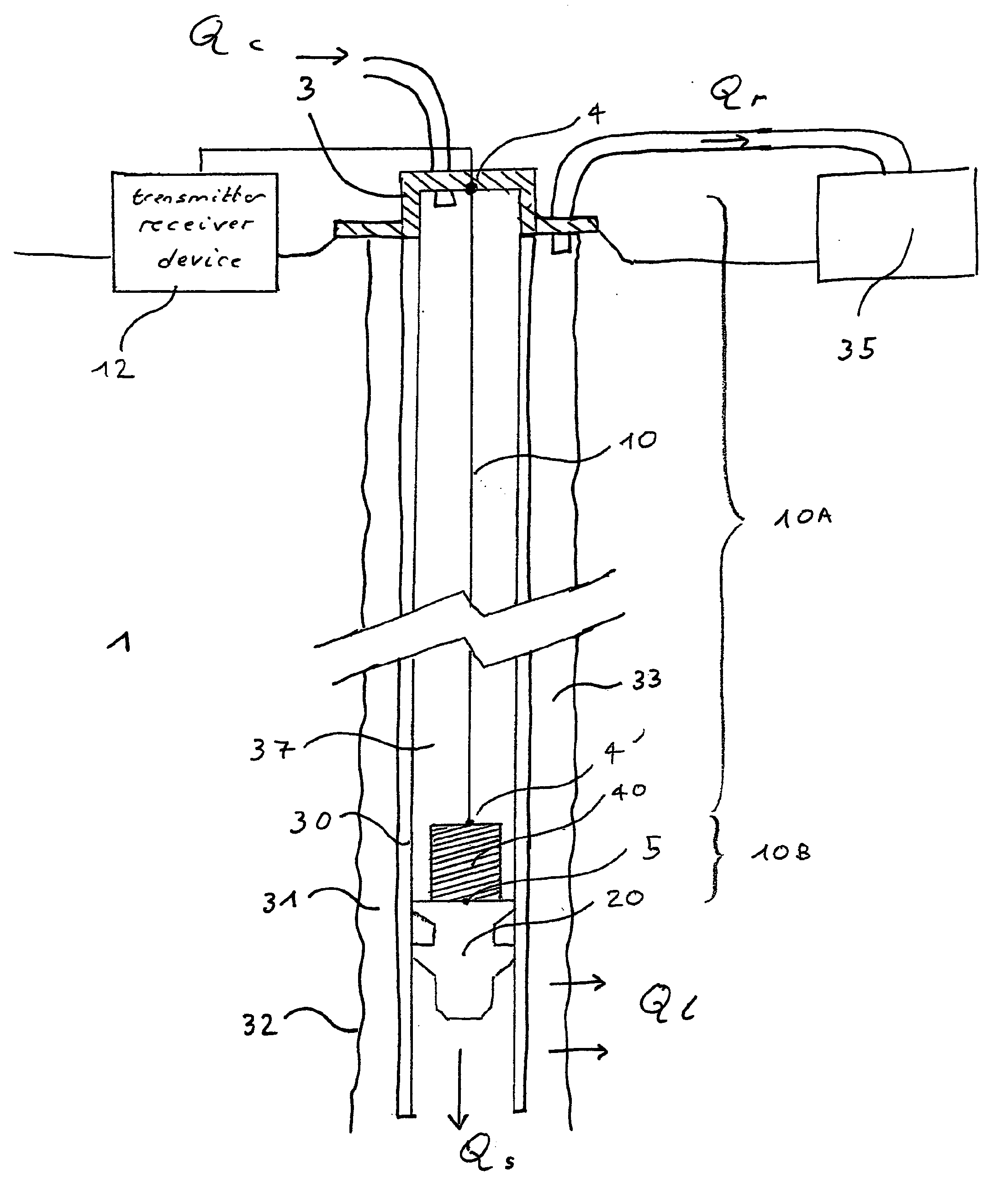
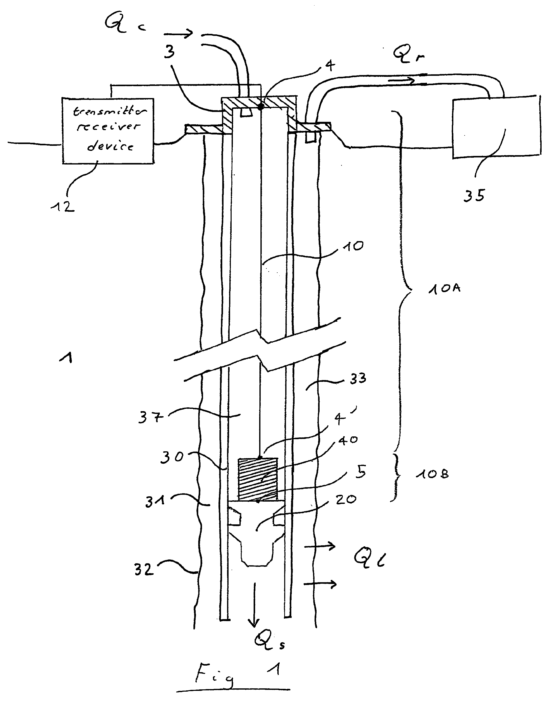
[0026]In a first embodiment, the reel is made with a short diameter of winding or more precisely a diameter short enough to be detected by the FBL (critical diameter dc or critical radius rc, 2 rc=dc); effectively the short diameter creates an attenuation detectable by the FBL. The reel diameter is short enough to stop the propagation of the optical pulse. The reel diameter able to stop the optical pulse is a function of the pulse wavelength. The reel being seen as the first major optical event, the FBL will measure the length of the deployed fiber up to the reel, i.e. the plug. However also, the diameter of the reel can not be too short; effectively reducing the diameter of the reel can limit the maximum measurable distance to an unacceptable value.

second embodiment

[0027]In a second embodiment, the reel has been specially modified so the reel presents a required minimum curvature short enough to be detected by the FBL. So, the reel can have various geometric shapes; importance is that within the various curvatures present in this reel, there is a minimum curvature (close to rc) which is the required curvature short enough to be detected by the FBL. For example, the shape of the reel can be ovaloid with a wanted curvature. The wanted curvature is short enough to stop the propagation of the optical pulse. The wanted curvature able to stop the optical pulse is a function of the pulse wavelength.

third embodiment

[0028]In a third embodiment, the reel is made with a diameter not necessarily short even large, unable to stop the optical pulse and use the method as described above. In this case an additional element (not shown on the FIGURE) is added on the second position 4′. The additional element corresponds to mechanical path through which the fiber is unwound and bends at a radius short enough to stop the optical pulse. In fact, the additional element creates the optical event. The additional element can be simply an angled tube or an angled collar through which the fiber passes. The radius able to stop the optical pulse is a function of the pulse wavelength. All these advantageous embodiments ensure that the major optical event is located at the second position and is detected more precisely.

[0029]In a fourth embodiment, the fiber is coiled like in the second embodiment at a constant and large radius R, which is greater than the critical radius rc but with a truncation T greater than 1 (tr...


PUM


Abstract

The invention provides apparatus for use in a wellbore (32) made of a casing (30) and an annular (33) with a fluid within, comprising: a reel (40) of wound optic fiber line (10) fixed to an object (20) within the casing, and a light transmitter/receiver device (12) able to generate a signal through the optic fiber line and to measure a change of said signal; wherein the optic fiber line is: (a) on a first position fixed to a reference point (4) linked to the light transmitter/receiver device, and is (b) on a second position unwound from the reel; wherein the light transmitter/receiver device is able to measure the change of said signal when occurring at the second position; and the apparatus having a system able to measure the flow rate of the fluid exiting the annular at the surface level Q.

Description

FIELD OF THE INVENTION[0001]The present invention generally relates to apparatus and methods for completing a well. Particularly, the present invention relates to apparatus and methods for locating a cement plug in the wellbore, measuring the return flow and estimating the leak of fluid into the formation.DESCRIPTION OF THE PRIOR ART[0002]After a well has been drilled, the conventional practice in the oil industry consists in lining the well with a metal casing. An annular area is thus formed between the casing and the formation. A cementing operation is then conducted in order to fill the annular area with cement. The combination of cement and casing strengthens the wellbore and facilitates the isolation of certain areas of the formation behind the casing for the production of hydrocarbons.[0003]A major difficulty of the cement operation is the possible existence of a U-tubing phenomenon generated by the density difference between the mud filling the wellbore and the injected cemen...

Claims


Application Information

Patent Timeline
Patent Type & Authority Applications(United States)
IPC IPC(8): E21B47/12E21B47/10
CPCE21B47/102E21B47/123G01B11/026E21B23/14E21B47/113E21B47/135
Inventor VIGNEAUX, PIERREGUILLOT, DOMINIQUE
Owner SCHLUMBERGER TECH CORP
Why Eureka
Try Eureka