Composite seat back frame

a composite seat and frame technology, applied in the field of modular composite seat back frames, can solve the problems of increasing cost reducing the overall weight of the airplane,

Inactive Publication Date: 2008-11-13
CUTTING DYNAMICS
View PDF22 Cites 45 Cited by
  • Summary
  • Abstract
  • Description
  • Claims
  • Application Information

AI Technical Summary

Benefits of technology

[0006]The invention is particularly directed to a seat back for use in airplanes and airplane applications made from a composition including carbon fiber and a thermoplastic. In one aspect, a seat back is provided having a composite body having a first end, a center section, and a second end that is thicker than the center section. The first end, the center section, and the second end comprise a plurality of layers of highly aligned fibers in a thermoplastic matrix. The seat back also is provided with a member extending outwardly from the second end and a leg secured along at least a portion of the second end. The leg is positioned along the member to form a cavity defined by the second end, the member, and the leg, the cavity capable of receiving a connecting rod for connecting the seat back assembly to a seat.

Problems solved by technology

For example, they have numerous and costly components that contribute to excessive assembly time and increased cost.
Also, they are often difficult to form the complex geometry required by to accommodate both the contours of the passenger as well as any devices such as trays, phones, monitors, and the like.
Furthermore, the overall weight of each conventional frame increases the overall weight of an airplane, thereby decreasing fuel efficiency.
While there have been attempts to replace aluminum with composite materials, those materials have not achieved the desired properties possessed by aluminum.
For example, such composite materials exhibit limited stiffness properties in comparison to aluminum and do not satisfy necessary safety standards.
While material stiffness can be compensated to some degree by shaping the components to enhance structural stability, the composite materials still lack the appropriate stiffness and therefore do not offer the potential for necessary improvements in structural performance.
Furthermore, such composite materials are typically thermosets that could pose potential safety issues regarding use on airplanes.

Method used


Image

  • Composite seat back frame
  • Composite seat back frame
  • Composite seat back frame

Examples


Embodiment Construction

[0016]While the present invention is described with reference to embodiments described herein, it should be clear that the present invention is not limited to such embodiments. Therefore, the description of the embodiments herein is merely illustrative of the present invention and will not limit the scope of the invention as claimed.

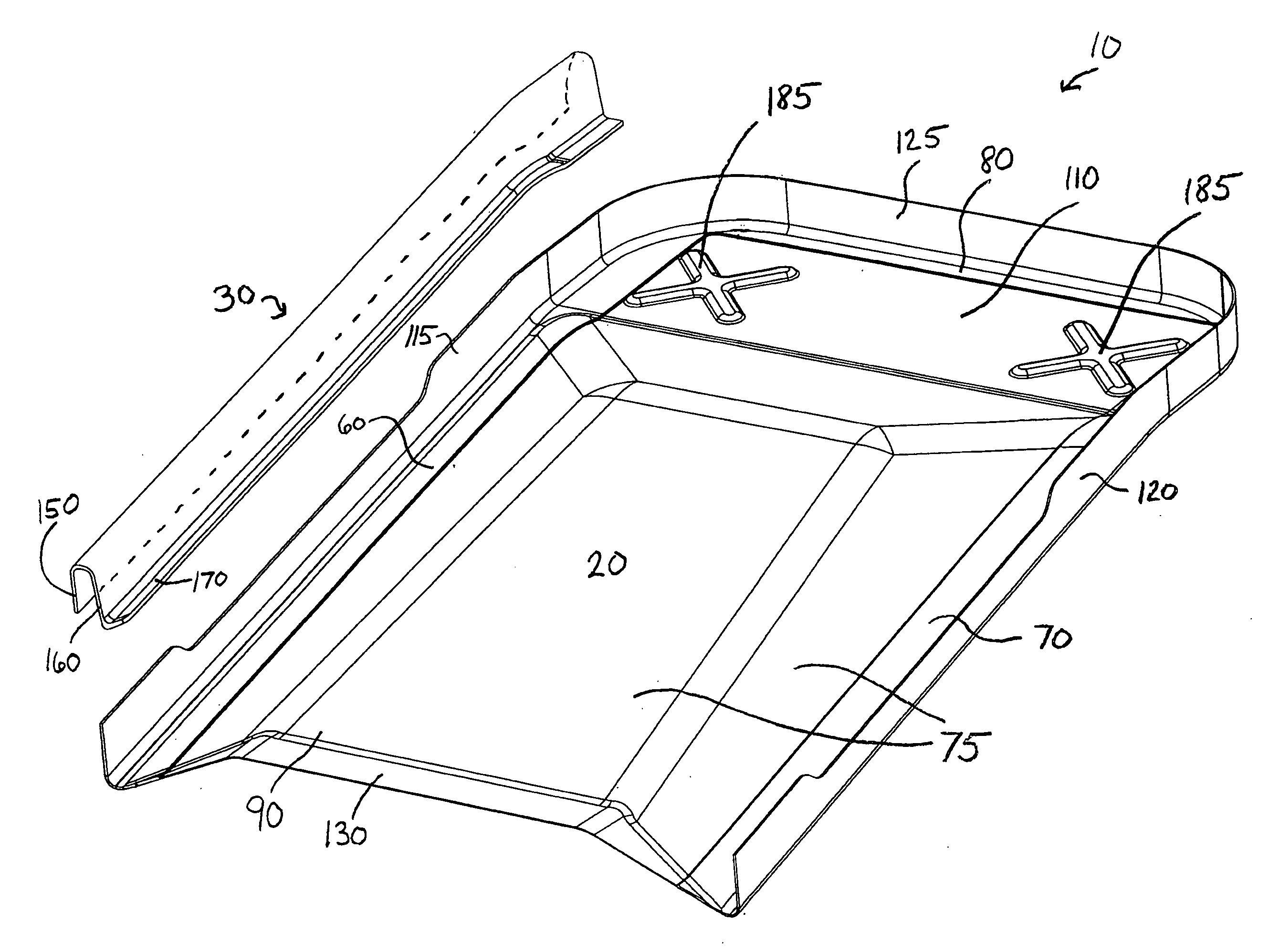
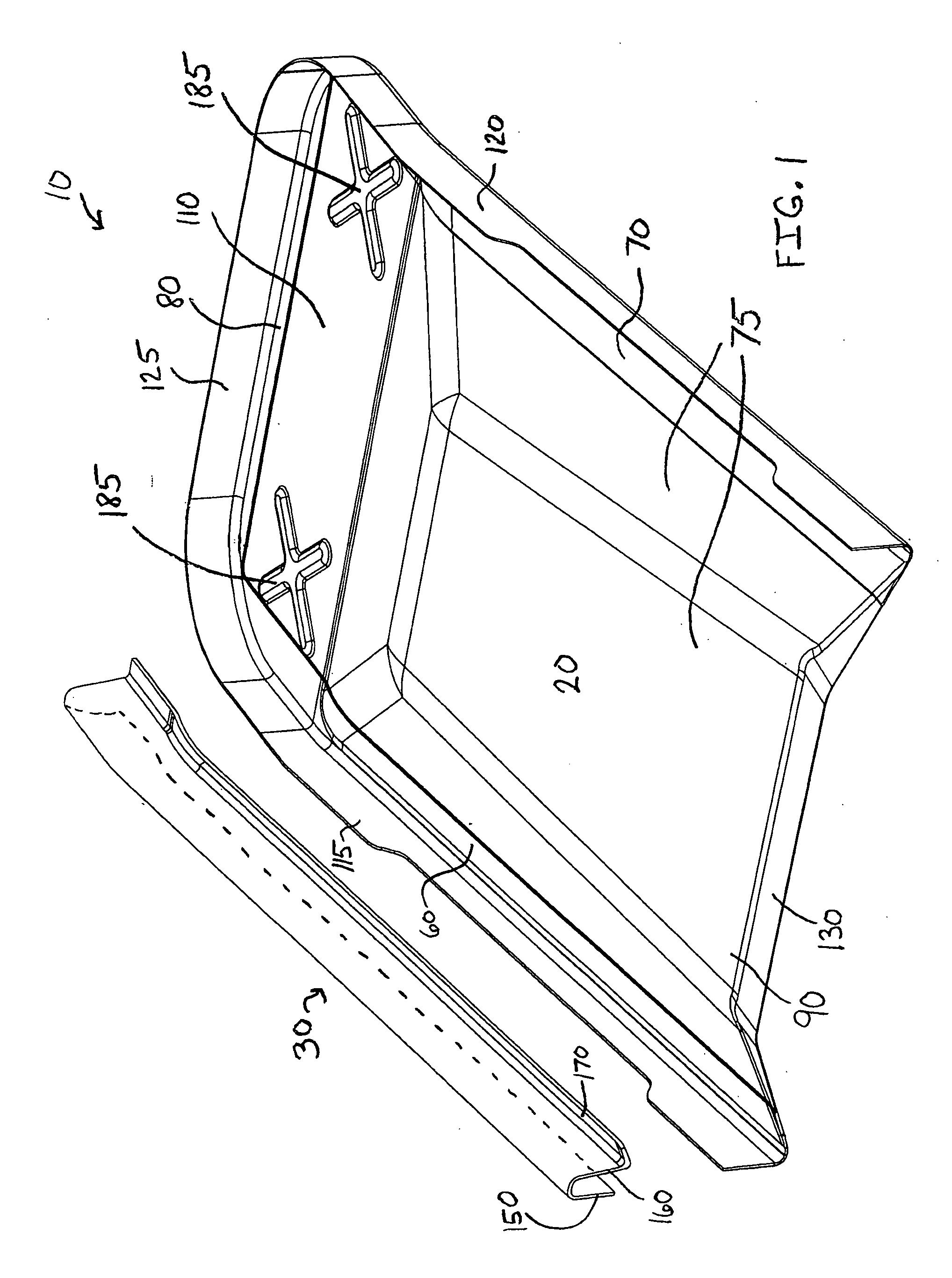
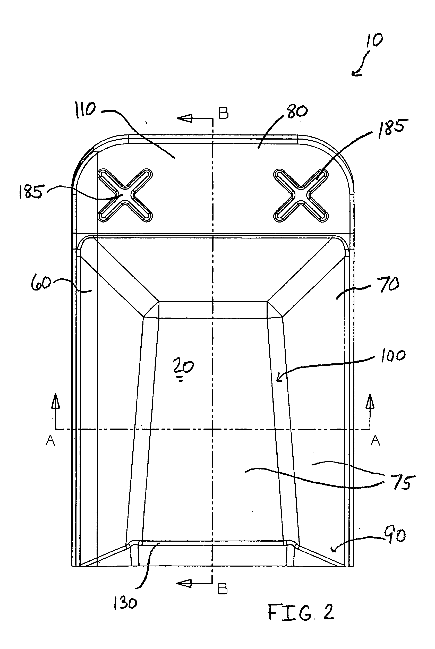
[0017]As generally described herein, FIGS. 1-7 illustrate embodiments of a composite seat back assembly 10 (hereinafter referred to as “the seat back 10”). In one embodiment, as shown in FIG. 1, the seat back 10 generally comprises a body 20 and one or more legs 30 secured thereto. The configuration of the body 20 and the leg 30 and the composite structure of one or both provides improved structural stability while decreasing the number of parts and overall weight of the seat back 10. Accordingly, the seat back 10 is capable of being utilized in airplanes. In a preferred embodiment, the body 20 and the leg 30 may be formed from composite blanks, as descr...


PUM


Abstract

A seat back is provided having a composite body having a first end, a center section, and a second end that is thicker than the center section. The first end, the center section, and the second end comprise a plurality of layers of highly aligned fibers in a thermoplastic matrix. The seat back also is provided with a member extending outwardly from the second end and a leg secured along at least a portion of the second end. The leg is positioned along the member to form a cavity defined by the second end, the member, and the leg, the cavity capable of receiving a connecting rod for connecting the seat back assembly to a seat.

Description

CROSS-REFERENCE TO RELATED APPLICATIONS[0001]This application claims benefit to Provisional Application No. 60 / 928,887 filed on May 11, 2007, which is hereby incorporated in its entirety by reference.FIELD OF THE INVENTION[0002]The present invention is generally related to modular composite seat back frames for use in passenger seat assemblies.BACKGROUND OF THE INVENTION[0003]In the airline industry, conventional seats and seat back frames have been formed from metals such as aluminum. Such conventional frames have a number of drawbacks. For example, they have numerous and costly components that contribute to excessive assembly time and increased cost. Also, they are often difficult to form the complex geometry required by to accommodate both the contours of the passenger as well as any devices such as trays, phones, monitors, and the like. Furthermore, the overall weight of each conventional frame increases the overall weight of an airplane, thereby decreasing fuel efficiency.[0004...

Claims


Application Information

Patent Timeline
Patent Type & Authority Applications(United States)
IPC IPC(8): A47C7/42
CPCB60N2/686
Inventor DEADRICK, MARK
Owner CUTTING DYNAMICS
Why Eureka
Try Eureka