Light-Guide Plate, Method of Manufacturing the Same and Display Apparatus Having the Same

a technology of lightguide plate and backlight assembly, which is applied in the direction of lightguides, lighting and heating apparatus, planar/plate-like light guides, etc., can solve the problems of decreased number of leds employed in the backlight assembly and increased distance between leds, so as to improve light efficiency

Active Publication Date: 2008-11-13
SAMSUNG DISPLAY CO LTD
View PDF5 Cites 37 Cited by
  • Summary
  • Abstract
  • Description
  • Claims
  • Application Information

AI Technical Summary

Benefits of technology

[0010]Embodiments of the present invention provide a light-guide plate capable of reducing an area of the dark region and improving the efficiency of light generated from a light source.
[0016]The second control patterns may have an oval-shaped cross-section. A pitch of each of the second control patterns may increase as a distance from a portion of the incident surface corresponding to a central portion of the light source increases. In another exemplary embodiment of the present invention, a height of each of the second control patterns may decrease as a distance from the first region increases.
[0022]According to the light-guide plate, light-control patterns are formed in regions of the incident surface sectioned according to a position of a light source and have shapes different from one another according to the regions. Therefore, in a backlight assembly having the light-guide plate and a display apparatus having the backlight assembly, a dark region formed between LEDs and a side portion of the light-guide plate may be substantially prevented and the efficiency of light may be improved.

Problems solved by technology

However, a distance between the LEDs increases as the number of the LEDs employed in the backlight assembly decreases.

Method used


Image

  • Light-Guide Plate, Method of Manufacturing the Same and Display Apparatus Having the Same
  • Light-Guide Plate, Method of Manufacturing the Same and Display Apparatus Having the Same
  • Light-Guide Plate, Method of Manufacturing the Same and Display Apparatus Having the Same

Examples


Embodiment Construction

[0037]Embodiments of the invention are described more fully hereinafter with reference to the accompanying drawings, in which embodiments of the invention are shown. Embodiments of this invention may, however, be embodied in many different forms and should not be construed as limited to the embodiments set forth herein. It will be understood that when an element or layer is referred to as being “on,”“connected to” or “coupled to” another element or layer, it can be directly on, connected or coupled to the other element or layer or intervening elements or layers may be present. Like numbers refer to like elements throughout.

[0038]Hereinafter, embodiments of the present invention will be explained in detail with reference to the accompanying drawings.

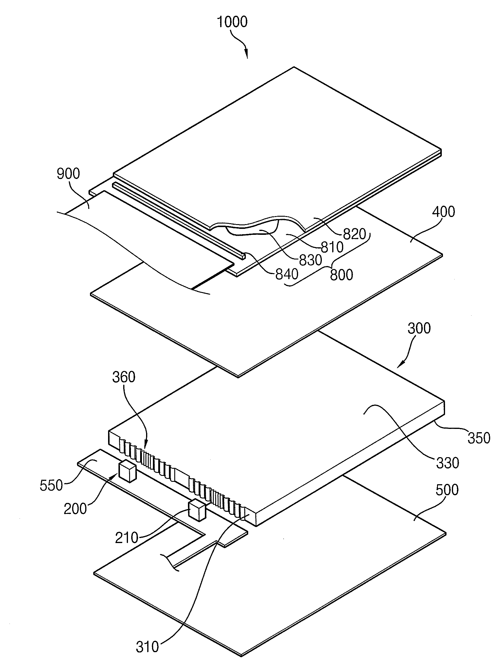
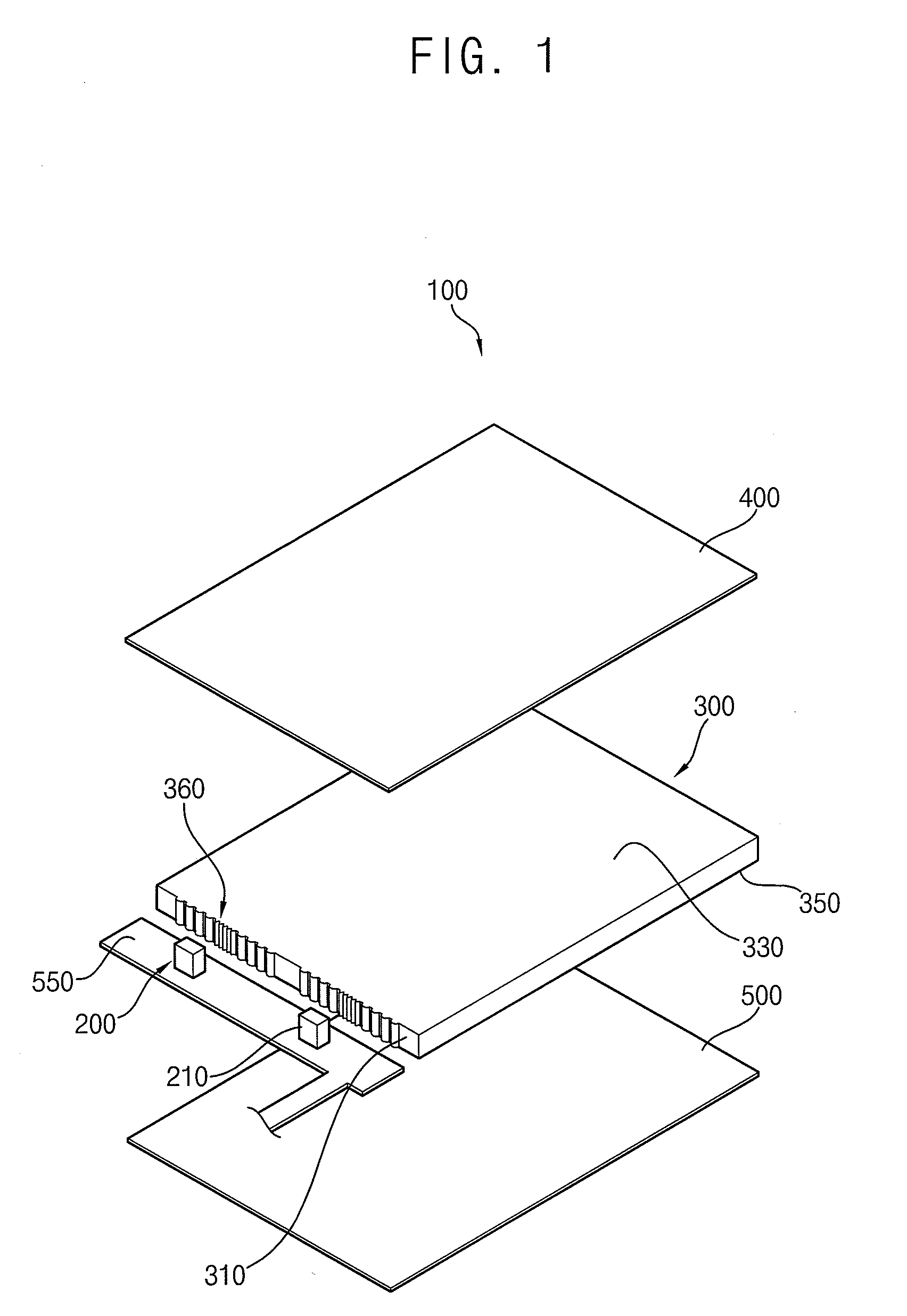
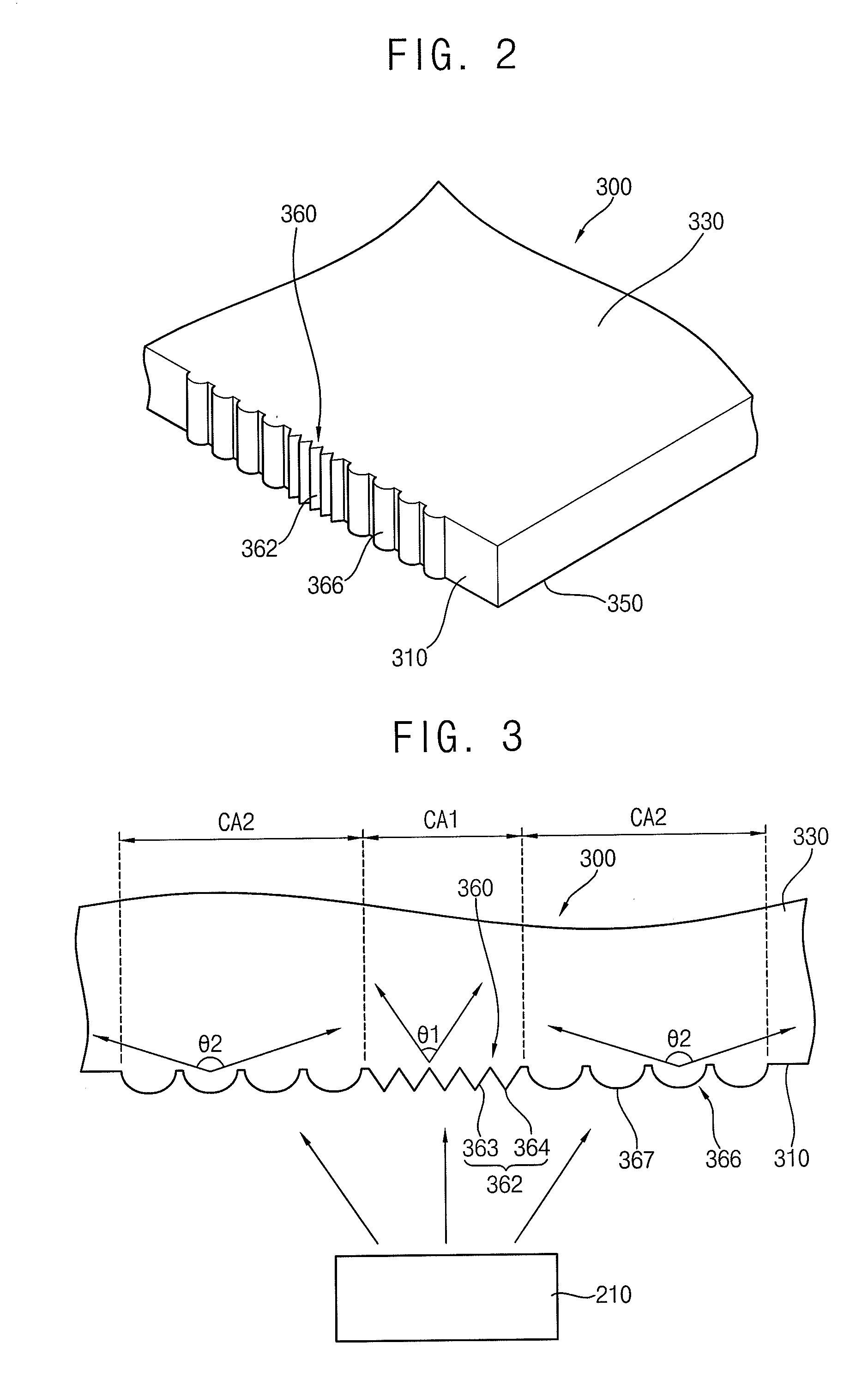
[0039]FIG. 1 is an exploded perspective view illustrating a backlight assembly according to an exemplary embodiment of the present invention. FIG. 2 is a perspective view illustrating an exemplary embodiment of the light-guide plate shown...


PUM

PropertyMeasurementUnit
display area DAaaaaaaaaaa
angleaaaaaaaaaa
beam angleaaaaaaaaaa

Abstract

A light-guide plate includes an incident surface, a emissive surface and a reflective surface. The incident surface includes a plurality of light-control patterns formed in sectioned regions of the incident surface. The light-control patterns have shapes different from one another according to the regions corresponding to a position of a light source. The emissive surface is extended from a side of the incident surface. The reflective surface is opposite to the emissive surface.

Description

CROSS-REFERENCE TO RELATED APPLICATIONS[0001]This application claims priority under 35 U.S.C. § 119 to Korean Patent Application No. 2007-44632, filed on May 8, 2007 in the Korean Intellectual Property Office (KIPO), the contents of which are herein incorporated by reference in their entirety.BACKGROUND OF THE INVENTION[0002]1. Field of the Invention[0003]The present disclosure is directed to a light-guide plate, a backlight assembly and a display apparatus having the light-guide plate. More particularly, the present disclosure is directed to a light-guide plate for guiding light generated from a light source, a backlight assembly and a display apparatus having the light-guide plate.[0004]2. Description of the Related Art[0005]A liquid crystal display (LCD) apparatus generally includes an LCD panel and a backlight assembly for providing the LCD panel with light.[0006]The backlight assembly includes a light source to generate light. Various light-emitting units may serve as the light...

Claims


Application Information

Patent Timeline
Patent Type & Authority Applications(United States)
IPC IPC(8): G02F1/1335F21V7/00F21V7/04
CPCG02B6/002F21V2200/20G02B6/0073G02B6/0068G02F1/1335
Inventor PARK, SANG-JUN
Owner SAMSUNG DISPLAY CO LTD
Why Eureka
Try Eureka