
Liquid crystal display device

a liquid crystal display and display device technology, applied in non-linear optics, instruments, optics, etc., can solve problems such as dark areas, achieve the effects of maximizing the transmittance of the liquid crystal display device, and reducing the dark area around the pixel

Active Publication Date: 2021-06-03
TCL CHINA STAR OPTOELECTRONICS TECH CO LTD
View PDF0 Cites 2 Cited by
  • Summary
  • Abstract
  • Description
  • Claims
  • Application Information

AI Technical Summary

Benefits of technology

The present invention is about improving the display quality of liquid crystal displays by adding a chiral agent that drives the rotation of liquid crystal molecules around the pixel, reducing dark area around the pixel. Additionally, by changing the angle between different components, the transparency of the display is maximized, resulting in a higher quality display.

Problems solved by technology

However, in the existing pixel structure, a peripheral area of the pixel display in the PSVA display mode may have a non-ideal condition, resulting in a dark area.

Method used


Image

  • Liquid crystal display device
  • Liquid crystal display device
  • Liquid crystal display device

Examples


Embodiment Construction

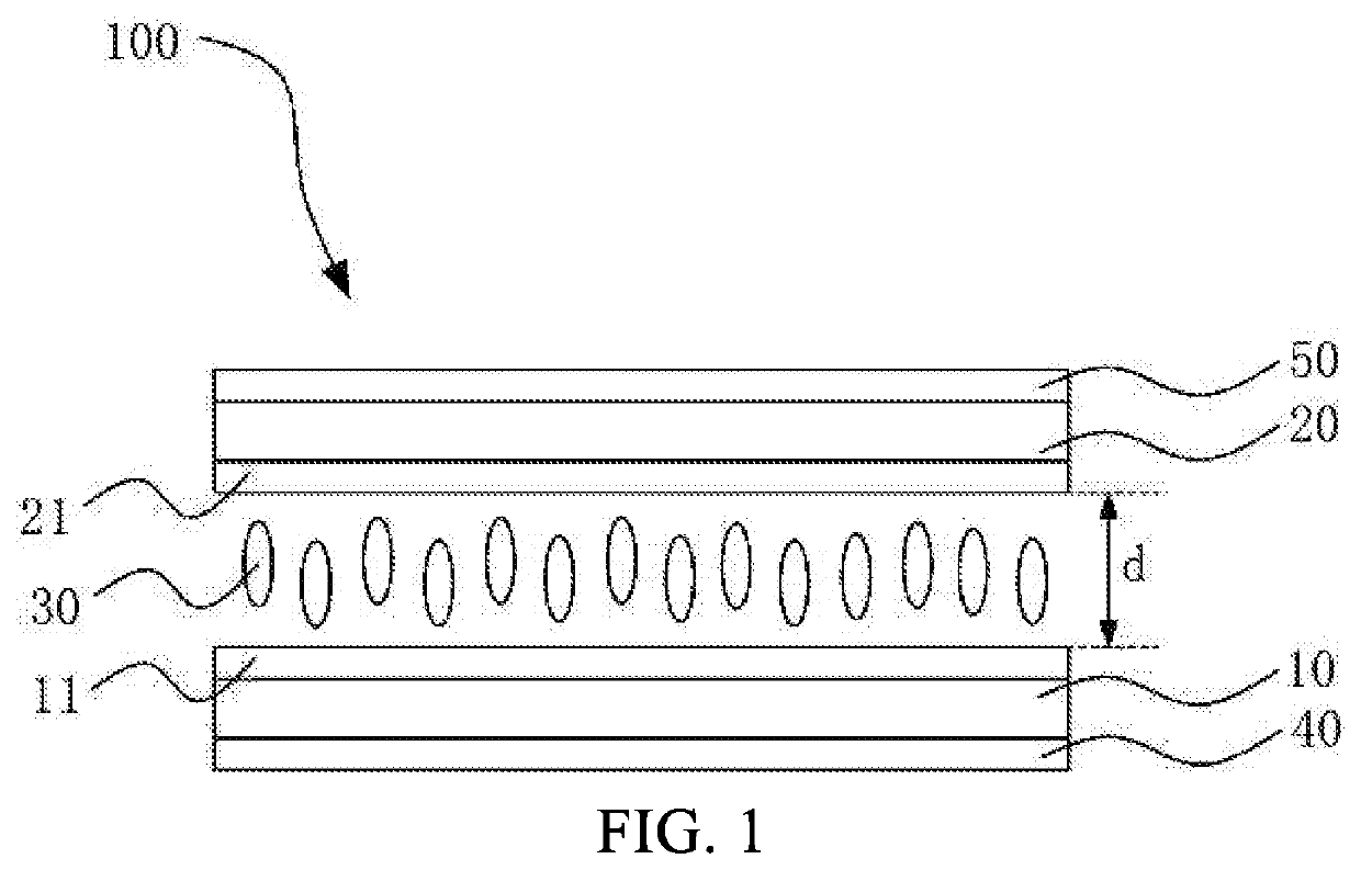
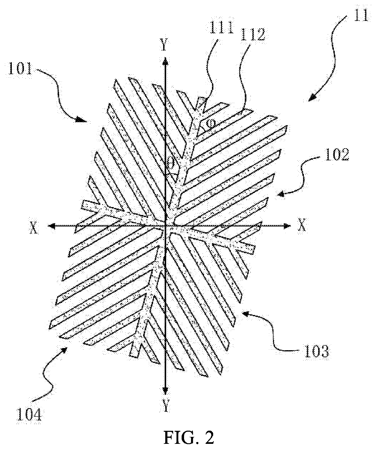
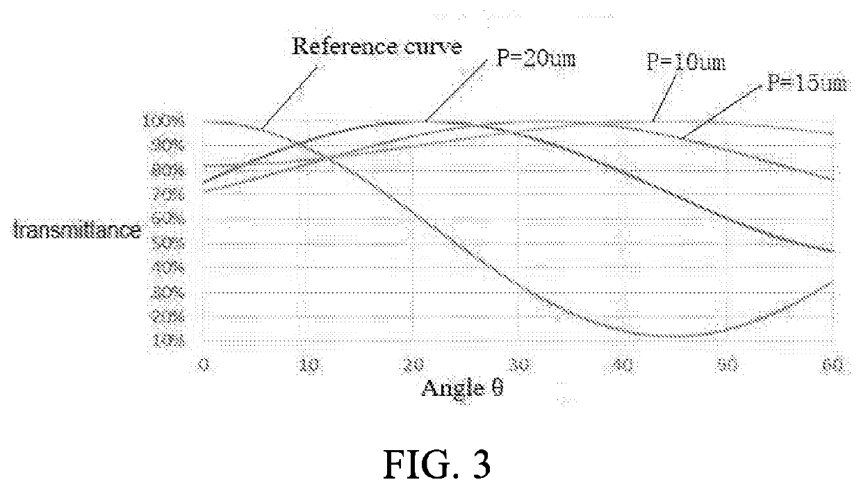
[0030]The following descriptions of the various embodiments are upon the attached figures, and are provided to illustrate the specific embodiments of the present disclosure that can be implemented. Directional terms mentioned in the present disclosure, such as “upper”, “lower”, “front”, “rear”, “left”, “right”, “inside”, “outside”, “lateral”, etc., refer to the directions of the attached figures. Therefore, the directional terms are used for the purpose of illustration and understanding of the present disclosure, rather than limiting the present disclosure. In the figures, structurally similar elements are labeled by the same reference numerals.

[0031]The present disclosure is directed to the display technical problem of the conventional liquid crystal display device, since the PSVA display mode is adopted, a dark area is generated around the pixel, which affects a transmittance of the product, thereby affecting the display. This embodiment can offset the defect.

[0032]As shown in FIG...


PUM

PropertyMeasurementUnit
optical path differenceaaaaaaaaaa
thicknessaaaaaaaaaa

Abstract

A liquid crystal display device includes a first substrate having a first electrode, a second substrate having a second electrode, a liquid crystal layer, a first polarizer, and a second polarizer. A chiral agent is added in a liquid crystal filled in the liquid crystal layer, a pitch of the liquid crystal is about 8-60 μm; an effective optical path difference of the liquid crystal is about 300-550 nm. By adding a chiral agent to the liquid crystal, changing the angle between the stem electrode and the branch electrode or the angle between the polarization axis of the polarizer and the stem electrode, the transmittance is maximized, thereby achieving high transmittance display.

Description

FIELD OF INVENTION[0001]The present disclosure relates to a field of display technologies, and in particular to a liquid crystal display device.BACKGROUND OF INVENTION[0002]Currently used liquid crystal displays are classified into twisted nematic (TN) mode, vertical alignment (VA) mode, in-plane switching (IPS) mode, and fringe field switching (FFS) mode, etc. The most commonly used technology in the VA display mode is polymer stabilized vertical alignment (PSVA), which has the advantages of high contrast and fast response. PSVA liquid crystal display technology has become the most extensive display technology at present. However, people have higher and higher requirements for display technology. Wider viewing angles and higher transmittance have always been important directions for the future development of display technology.[0003]The PSVA display mode needs to add a UV process in the cell process, that is, ultraviolet (UV) irradiation is performed under power-on conditions. So, ...

Claims


Application Information

Patent Timeline
Patent Type & Authority Applications(United States)
IPC IPC(8): G02F1/1343G02F1/1335
CPCG02F1/134309G02F1/133528G02F1/137G02F1/13775G02F1/1393G02F1/133707
Inventor CHEN, XINGWU
Owner TCL CHINA STAR OPTOELECTRONICS TECH CO LTD
Learn More